This page defines characteristic values to contact between two geometry entities. Roller, Crown Roller, Flange, V Pulley, Ribbed V-Pulley, and Timing Pulley supported in RecurDyn/Belt are using this page.
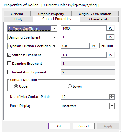
Figure 1 Roller property page [Contact Properties page]
Contact normal force
The contact normal force is obtained by

where, k and c are the stiffness and damping
coefficients which are determined by an experimental method, respectively.  and
and  are a penetration and
time differentiation of the penetration, respectively. The exponents
are a penetration and
time differentiation of the penetration, respectively. The exponents  and
and  generates a non-linear contact
force and the exponent
generates a non-linear contact
force and the exponent  yields an indentation damping effect.
•Characteristic: Defines the contact properties such as the stiffness coefficient, damping coefficient, and friction coefficients. Also, these coefficients can be given as user-defined spline curves.
•Stiffness Coefficient: Specifies a stiffness coefficient for the contact normal force.
•Stiffness Spline: The spline shows the contact normal force for the penetration. For more information, click here.
•Damping Coefficient: Specifies a damping coefficient for the contact normal force.
•Damping Spline: The spline shows the contact normal force for the velocity of penetration. For more information, click here.
•Dynamic Friction Coefficient: Specifies a dynamic friction coefficient for the contact friction force. It has three options.
o Dynamic Friction Coefficient: The constant friction coefficient is applied.
o Friction Force Spline: The spline shows the fiction force for the relative velocity. It is recommended to use the spline that x and y values are defined as positive.
o Friction Coefficient Spline: The spline shows the friction coefficient for the relative velocity.
•More: Specifies some friction coefficients for the contact friction force. Refer to Friction.
•Stiffness and Damping Exponent: Generates a non-linear contact normal force.
•Indentation Exponent: Yields an indentation damping effect. When the penetration is very small, the contact force may be negative due to a negative damping force, which is not realistic. This situation can be overcome by using the indentation exponent greater than one.
•Contact Direction
•Upper: If pulley and roller are contacted with the upper side of its belt, check this direction. The upper side means a +Y direction on its belt local orientation. Ex) The top surface of a timing belt (parameter type) is on a +Y direction, therefore this Upper is checked for the top surface to a pulley/roller contact case.
•Lower: If pulley and roller are contacted with the lower side of its belt, check this direction. The lower side means a -Y direction on its belt local orientation. Ex) The tooth of a timing belt (parameter type) is on a -Y direction, therefore this Lower is checked for the tooth surface to a pulley/roller contact case.
•No. of Max Contact Points : Defines the number of max contact point for output. User can define this value from 1 to 5000. This value only affects Force Display and RPLT data about the contact points. The default value is 10.
•Force Display : Graphically displays the all contact force vectors (the sum of the normal and tangential contact force) at each contact point up to the “No. of Max Contact Point”.