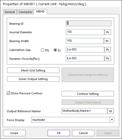
The user can modify the property of MEHD in the following dialog box.

Figure 1 MEHD property page [MEHD page]
•Bearing ID
•Journal Diameter: Defines a journal diameter of EHD Rotational Lubrication.
•Bearing Width: Defines a bearing width of EHD Rotational Lubrication.
•Lubrication Gap: Defines a characteristic of EHD.
•[%]: Defines this value using the percentage method.

Eq.1 Equation of Lubrication Gap
•[L]: Defines this value as length unit.

•Dynamic Viscosity [Pa.s]: Defines lubricant viscosity.
•Mesh Grid Setting: Defines mesh grids for Oil Hole and Groove Effects. For more information, click here.
•Search/View Node For MForce: Defines nodes in which MForce resulting from the EHD pressure is applied. If the shaft part is RFlex body, this function is activated. For more information, click here.
•Solver Output Setting: Defines information to write an output file. In the case of MEHD, this function is activated. For more information, click here.
•Show Pressure Contour Animation: If this option is checked, the user can see the EHD contour during the playing animation.
•Contour Setting: Defines the EHD Contour information. For more information, click here.
•Output Data Export: Displays on Scope or exports for the film thickness and file pressure. For more information, click here.
•Output Reference Marker: Selects a reference marker for EHD force result. The default marker is a base marker of EHD.
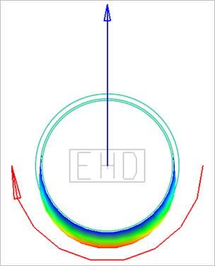
•Force Display: The user can graphically display the resultant force vector on the Working Window.

Figure 2 Force Display of MEHD