The user can control the mesh grid region and Oil Hole & Groove Effects.
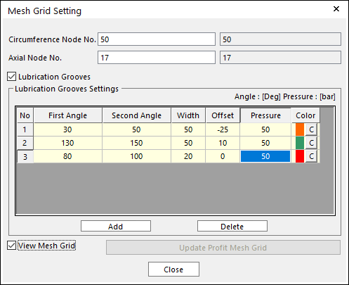
Figure 5 Mesh Grid Setting in MEHD Type
•Circumference Node No.: “N”
•Axial Node No.: “M”
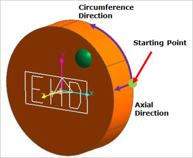
Figure 6 Defining Circumference Node No. and Axial Node No.
•Lubrication Grooves: If this option is checked, the user can give lubrication grooves effects.
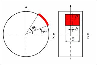
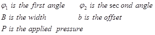
Figure 7 Defining Oil hole and Groove Region
•Pressure [bar]: Defines the pressure value. The unit of this value is bar regardless of RecurDyn unit.
•Color: Displays selected nodes as this color if the user checks View Nodes.
•Update Profit Mesh Grid: Updates the mesh grid number as the groove region.
•View Mesh Grid: Shows the mesh grid in the Working Window.
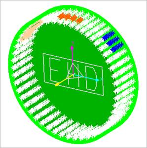
Figure 8 View Mesh Grid