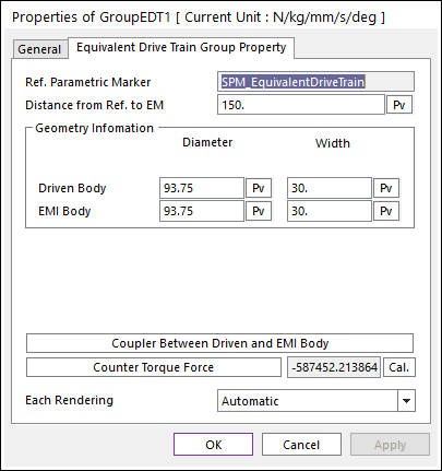
Click the right mouse button on the EDT component to choose Properties of EDT. The user can modify the property of EDT in following dialogs.
Direct Drive Type

Figure 1 Properties of GroupEDT dialog box [Direct type]
•Reference Parametric Marker: Controls the position of EDT. It is also special parametric marker.
•Geometry Information: Refers to Geometry information.
•Click Coupler Between Driven and EMI Body in Figure 1. The Properties of EDT TimingCoupler is showed up.
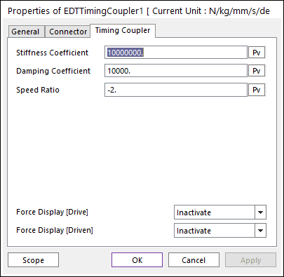
Figure 2 Properties of EDT Timing Coupler
•Each Rendering: The selected mode can be displayed in Each Render mode. For more information, click here.
Gear Drive Type
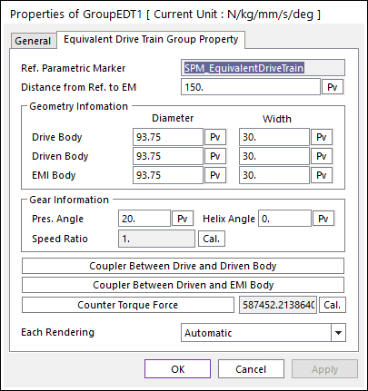
Figure 3 Properties of GroupEDT dialog box [Gear type]
•Reference Parametric Marker: Controls the position of EDT. It is also special parametric marker.
•Geometry Information: Refers to Geometry information.
•Click Coupler Between Drive and Driven Body in Figure 3. The Properties of EDTTimingCoupler1 is showed up.
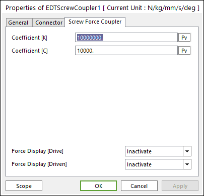
Figure 4 Properties of EDT ScrewCoupler [Gear type]
•Click Coupler Between Driven and EMI Body in Figure 3. The Properties of EDTTimingCoupler1 is showed up.
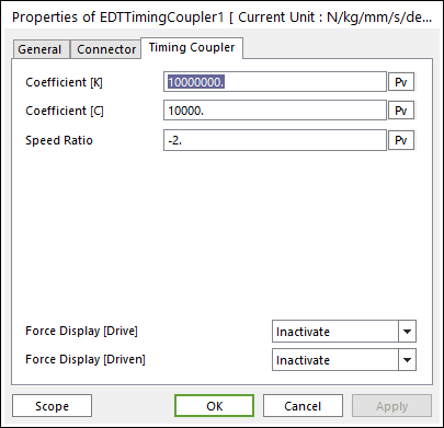
Figure 5 Properties of EDT TimingCoupler [Gear type]
•Each Rendering: The selected mode can be displayed in Each Render mode. For more information, click here.
Belt Drive Type
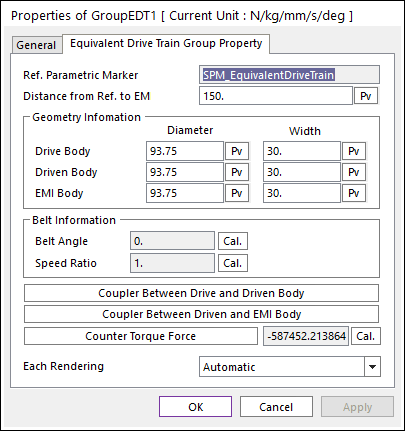
Figure 6 Properties of GroupEDT dialog box [Belt drive type]
•Reference Parametric Marker: Controls the position of EDT. It is also special parametric marker.
•Geometry Information: Refers to Geometry information.
•Click Coupler Between Drive and Driven Body in Figure 6. The Properties of EDTTimingCoupler1 is showed up.
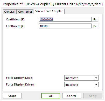
Figure 7 Properties of EDT ScrewCoupler [Belt type]
•Click Coupler Between Driven and EMI Body in Figure 6. The Properties of EDTTimingCoupler1 is showed up.
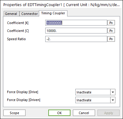
Figure 8 Properties of EDT TimingCoupler [Belt drive type]
•Each Rendering: The selected mode can be displayed in Each Render mode. For more information, click here.