This page allows the user to control the output files after simulation.
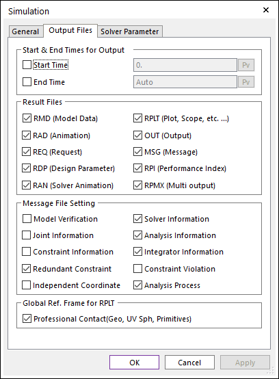
Figure 1 Simulation dialog box [Output Files]
•Start & End Times for Output: Defines the time range of the plot results. For example, if the user defines the range as the start time with 1 and the end time with 2, RecurDyn reports the plot result from 1 sec to 2 sec after simulation.
•Start Time: Defines the start time of plot results.
•End Time: Defines the end time of plot results.
•Result Files: If the user checks these options, RecurDyn creates the following result files.
|
File Name |
File Format |
Created by |
Contents |
|
RMD (Model Data) |
Text |
RecurDyn/Modeler |
All of the model data that are used by RecurDyn/Solver to run a simulation. |
|
RPLT (Plot, Scope, etc …) |
Binary |
RecurDyn/Solver |
Result data for Plot and Scope. |
|
RAD (Animation) |
Binary |
RecurDyn/Modeler |
An animation result for dynamic analyses, a state of static equilibrium, eigenvalue analyses, and a FRA analysis. The animation flag can be activated by this file. When importing the RAD file, the RPLT file related to the RAD file is imported automatically. |
|
OUT (Output) |
Text |
RecurDyn/Solver |
Initial conditions and eigen outputs. For more information, click here. Creation of the mck.m file is also determined by this option. |
|
REQ (Request) |
Text |
RecurDyn/Solver |
Result data about defined requests. For more information, click here. |
|
MSG (Message) |
Text |
RecurDyn/Solver |
A solver message. For more information, click here. |
|
RDP (Design Parameter) |
Text |
RecurDyn/Modeler |
Design parameters for performing Parametric Study. For more information, click here. |
|
RPI (Performance Index) |
Text |
RecurDyn/Modeler |
Result data about performance indexes for performing Parametric Study. |
|
RAN (Solver-Generated Animation) |
Binary |
RecurDyn/Solver |
An animation result. The animation flag can be activated by this file. In case of the standalone solver, the RAD file does not exist because there is no RecurDyn/Modeler. Therefore, the RAN file should be created the animation results. Additionally, when importing the RAN file, the RPLT file related to the RAN file is imported automatically. |
|
RPMX (Multi Output) |
Text (XML) |
RecurDyn/Solver |
This file has solver commands with the path of animation result files. For more information about solver commands, click here. If user want to simulate multi-analysis using the scenario analysis, it helps to check animation result. It needs that RAN file creation option must be checked. |
•Additional Result Files: If the simulation is started, RecurDyn creates the following result files. The user could not control whether or not to create these files.
|
File Name |
File Format |
Created by |
Contents |
|
DAT |
Text |
RecurDyn/Solver |
Result data of the converting file to read in RecurDyn/Solver from the RMD file. (After performing the simulation successfully, it will be deleted at the end of simulation.) |
|
DBK |
Binary |
RecurDyn/Solver |
All body data of the converting file to read in RecurDyn/Solver from the RMD file. (After performing the simulation successfully, it will be deleted at the end of simulation.) |
|
INF |
Text |
RecurDyn/Solver |
Input debug information for RecurDyn/Solver. (After performing the simulation successfully, it will be deleted at the end of simulation.) |
|
LOG |
Text |
RecurDyn/Solver |
The solver version information and additional solver information. |
|
FPLT |
Binary |
RecurDyn/Solver |
Result data for Plot after performing a Frequency Response Analysis. To see the FPLT file, the FRA Plot function should be used. For more information, click here. |
|
FRQ |
Text |
RecurDyn/Solver |
Eigen values. For more information, click here. |
|
FCP |
Binary |
RecurDyn/Solver |
The contacted patch information and the contact pressure. This file is used to see the Contour result. For more information, click here. |
|
GSTRN |
Binary |
RecurDyn/Solver |
Plastic strains at gauss points. This file is used for calculating plastic strains. |
|
GSTRS |
Binary |
RecurDyn/Solver |
Plastic stresses at gauss points. This file is used for calculating plastic stresses. |
|
MMX |
Binary |
RecurDyn/Solver |
The minimum and maximum values of stress and strain of RFlex and FFlex bodies for each time step. This file is used to see the Contour result. |
•Message File Settings: If the user checks these options, RecurDyn/Solver writes the following information in the MSG (Message) file.
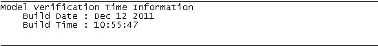
•Model Verification
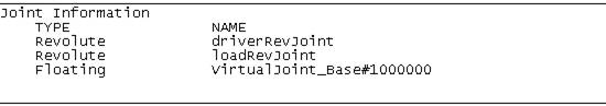
•Joint Information
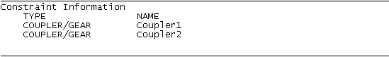
•Constraint Information
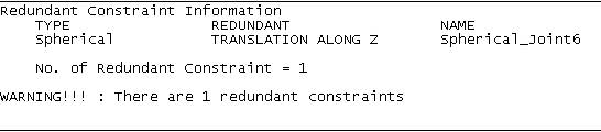
•Redundant Constraint
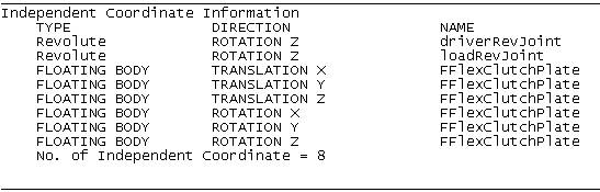
•Independent Coordinate
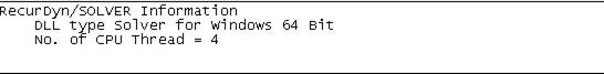
•Solver Information
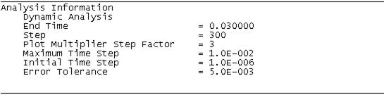
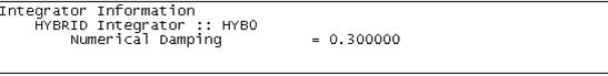
•Analysis Information
•Integration Information
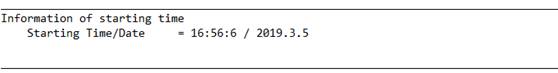
•Information of starting time
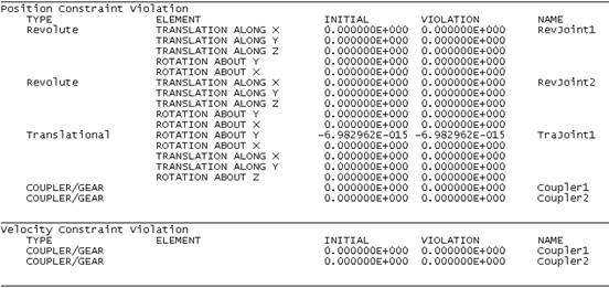
•Constraint Violation
•Analysis Process
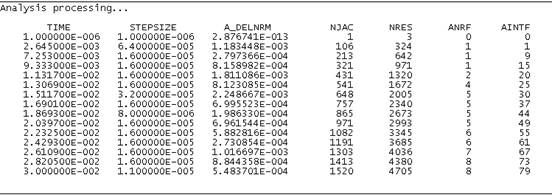
o A_DELNRM: The Accumulated Total Norm
o NJAC: The Total Number of Jacobian Evaluations
o NRES: The Total Number of Residual Evaluations
o ANRF: The Accumulated Total Number of Newton Raphson Failures (The Maximum Iteration is 10 in RecurDyn.)
o AINF: The Accumulated Total Number of Integration Failures (During the Newton-Rhapson Iterations, if the total norm of the current step is greater than that of the previous step, RD counts this case as the number of Integration Failure.)
•Global Reference Frame for RPLT: If the user checks this option, then the reference frame is setting to the Ground.Inertia Marker for the plot data on the RPLT file.
•Professional Contact (Geo, UV Sph, Primitives): If the user checks this option, then the summation contact force plot data is calculated with respect to the Ground.Inertia Marker.
o Geo contacts
|
No. |
Contact Name |
|
1 |
Geo Surface |
|
2 |
Geo Sphere |
|
3 |
Geo Cylinder |
|
4 |
Geo Curve To Surface |
|
5 |
Geo Curve |
|
6 |
Geo Circle |
o UV Sphere contact
o Primitive contacts
|
No. |
Contact Name |
|
1 |
Sphere To Sphere |
|
2 |
Sphere In Sphere |
|
3 |
Sphere To Cylinder |
|
4 |
Sphere In Cylinder |
|
5 |
Sphere To Cone |
|
6 |
Sphere In Cone |
|
7 |
Sphere To Box |
|
8 |
Sphere In Box |
|
9 |
Sphere To Torus |
|
10 |
Sphere In Torus |
|
11 |
Sphere To Arc Revolution |
|
12 |
Sphere To Arc Extrusion |
|
13 |
Cylinder To Cylinder |
|
14 |
Cylinder In Cylinder |
|
15 |
Cylinder To Box |
|
16 |
Cone To Cylinder |
|
17 |
Cone To Cone |
|
18 |
Cone In Cone |
|
19 |
Cam 2D |
|
20 |
CamLine 2D |
|
21 |
Circle To Circle |
|
22 |
Circle In Circle |
|
23 |
Circle To Curve |
|
24 |
Curve To Curve |