Animation Status
Animation Status displays the selected component of the contour type.
Type
Type allows to select a contour type by choosing one of in the pull-down menu. The contour type supports several entities such as Displacement, Strain, Stress, and Contact Pressure, Acoustics ERP.
Component
Component allows to select a contour type component by choosing one of in the pull-down menu.
•The Displacement outputs are TX, TY, TZ, TSum, RX, RY, RZ, and RSum.
•Each component is measured in the Node Reference Frame of Reference Node.
•The displacement output names are defined as follows:
o T* is the translation displacement
o R*is the rotational displacement.
o Tsum is the magnitude of translational displacements.
o Rsum is the magnitude of rotational displacements.
•Definitions
o Translation displacement
Where, A_r,t and A_r,0 are all orientation matrices on the current simulation time t and initial time 0.0sec, respectively.
r_p,t and r_p,0 are all arbitrary node position vector with respect to flexible body reference frame on the current simulation time t and initial time 0.0sec , respectively.
r_r,t and r_r,0 are all position vector of reference node with respect to flexible body reference frame on the current simulation time t and initial time 0.0sec, respectively.
o Rotation displacement
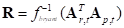
Where, A_r,t and A_p,t are all orientation matrices of the reference node and an arbitrary node on the current time, respectively.
F^-1_bryant means an inverse the Bryant angle (=EulerAngle 123).
•Orientation Reference Marker
o The orientation reference marker function is available only for the displacement type function. If the user set a maker for the Orientation Reference Marker, then the Displacement results are calculated with following coordinate transformation.
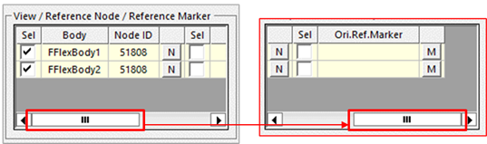
Figure 1 Orientation Reference Marker option on the Contour Dialog
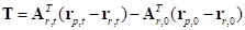
o Translation and rotation displacements
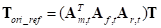
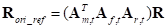
Where, T, R, T_ori_ref, and R_ori_ref are all the contour displacements. T and R is the default calculation value on the above equation. T_ori_ref and R_ori_ref are the final contour displacement results. This option is just applied coordinate transformation to the orientation reference marker with already computed displacements vector.
A_m,t is orientation matrix of the orientation reference marker with respect to global on current time t.
A_f,t is orientation matrix of the flexible body reference frame with respect to global on current time t.
A_r,t is orientation matrix of the reference node with respect to the flexible body reference frame on current time t.
•The Strain outputs are EX, EY, EZ, EXY, EYZ, EZX, E1, E2, E3, EINT, EMISES while the Stress outputs are SX, SY, SZ, SXY, SYZ, SZX, S1, S2, S3, SINT, and SMISES.
•In the case of FFlex Body, each component is measured in the Reference Marker defined in Output Regenerator. The default is Ground.Inertia Marker. For more information, click here.
•In the case of RFlex Body, each component is measured in the Body Reference Frame of RFlex Body. The reference frame cannot be modified.
•To see the outputs for these components, the user has to check options in Output File Setting.
•The stress and strain output names are defined as follows:
o E*: strain
o S*: stress
o *X: x direction
o *Y: y direction
o *Z: z direction.
o *XY: xy shear
o *YZ: yz shear
o *ZX: zx shear.
o *1: first principal
o *2: second principal
o *3: third principal
o *INT: intensity
o *MISES: von-mises
o _E: elastic strain
o _P: plastic strain
o _T: total strain
o _ THERMAL: thermal strain
•The Contact Pressure outputs are CP_EL and CP_CP. The contact pressure output names are defined as follows:
•CP_EL: Contact pressure - Element formulation type
o Contact pressure is computed using the element formulation of a contacted patch. The value is defined as a stress component of negative contact normal direction on the stress tensor.
o This component is activated when using following entities.
|
Product |
Supported Entity |
|
FFlex |
FSurface To Surface Contact |
|
FSurface To FSurface Contact | |
|
Geo Contact | |
|
RFlex |
Geo Contact |
•CP_CP: Contact pressure - Contact force type
o Contact pressure is computed that the contact normal force was divided by area of the contacted patch.
o This component is activated when using following entities.
|
Product |
Supported Entity |
|
FFlex |
FSurface To Surface Contact |
|
Geo Contact | |
|
RFlex |
Geo Contact |
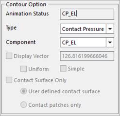
Figure 1 Contact Pressure in the Contour dialog
Display Vector
Display Vector shows the vector of the principle strain/stress as the arrows.
•Display Vector: Is activated in case of selecting a component among E1, E2, E3 or S1, S2, S3.
•Display Vector Size: Displays the proper size of the vector according to the element length of a flexible body.
•This size is used the system unit of the assembly mode of RecurDyn.
•It is possible to input the value in this section when the user want to change the vector size.
•The designated value can be used as the size of the maximum vector in case of the maximum stress or strain on the contour results. So, the size of other vectors can be calculated automatically in GUI based on the defined maximum size as shown in the Figure 2 below.
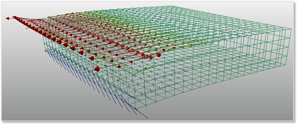
Figure 1 The vector display of the principle stress(S1)
•The principle stress or strain in case of tension has the plus value, and its vector shows that the arrow heads are placed in the opposite directions each other in the point of a node. On the contrary, in case of compression, it has the minus value, and its vector shows that two arrows are looking at each other at a node as shown the Figure 3 below.
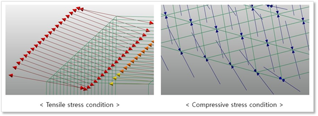
Figure 2 The comparison of two conditions
•Uniform: Displays all vector as the same size that is defined in the Display Vector regardless of the magnitude of principal strain or stress.
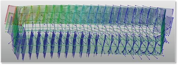
Figure 3 The applying the Uniform option to the vectors
•Simple: Shows all vectors as the lines instead of the shapes.
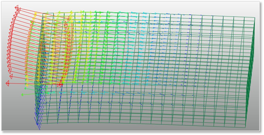
Figure 4 The applying the Simple option to the vectors
Note
RecurDyn recommends using the higher OpenGL version than 4.
Contact Surface Only
Contact Surface Only uses to view the stress of contour on the contact surface
•User defined contact surface: Displays Contour to the patch set defined by the contact surface.
•Contacted patches only: Displays Contour to the patches generating the real contact in the patches defined by the contact surface. The FFlex contact supported this option is as follows.
|
Product |
Supported Entity |
|
FFlex |
FSurface To Surface Contact |
|
FSurface To FSurface Contact | |
|
Geo Contact |
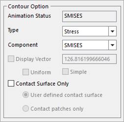
Figure 5 Contact Surface Only in the Contour dialog
Note
When a FFlex body consists of shell elements, the user must use the Contact force type because the Element formulation type will not be derived the correct results. The user can see the contact pressure contour data by using the Export function of Post Process in FFlex. The exported data shows the contact pressure results of the patch composed of nodes. However, because the user cannot see the patch information, you should find out the contact pressure of each patch by using node ID in the exported data.
When the contact patches are searched, the all connected contact patches of a node, in which a contact force is generated, are added in the case of Geo contact. As a result, the contacted patches are little different from the “FSurface To Surface” and “FSurface To FSurface” cases.