Before simulating a model including FFlex body, the user can set state of the output files such as the ERD and the SRD file by using this function.
Also, when finishing the simulation of the model, the output files such as the ERD and the SRD file can regenerate by using Output File Regenerator.
This function is useful such as the following cases.
•Case 1) The user wants to view the contour display of top/bottom without repeating a simulation
•Case 2) The user wants to view the contour display of specific Reference frame without repeating a calculation.
•Case 3) The user wants to reduce the animation file (*.rfa) size with the float type.
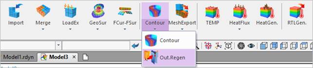
Figure 1 Out.Regen icon of the FFlex group in the Flexible tab
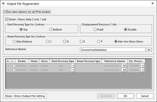
Figure 2 Output File Regenerator dialog box
•Set same options for all FFlex bodies
•If this option is checked, Regenerator sets the options for all FFlex Bodies. (The default is checked.)
•Recover Data (*.erd, *.srd)
•If this option is checked, the user can recover the strain and stress using the ERD and SRD result files (The default is checked).
•If this option is unchecked, the user cannot acquire the recover data and see the contour animation.
•Shell Recovery Type for Contour: Selects the recovery type of calculating stresses and strains on the shell element. The top of shell is identified by the ordering of the nodes. The shell side that is visible at the nodes ordered in a counterclockwise direction is the top of the shell.
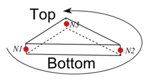
Figure 3 Shell top and bottom for Shell3
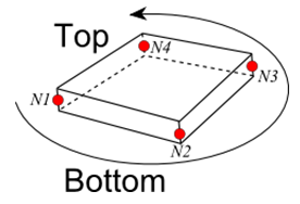
Figure 4 Shell top and bottom for Shell4 and Shell9
•Top: Stresses and strains reported by RecurDyn correspond to the top surface of shell elements. (This is default.)
•Bottom: Stresses and strains reported by RecurDyn correspond to the bottom surface of shell elements.
•Beam Recovery Type for Contour: Selects the recovery type of calculating stresses and strains on the Beam2 element.
•Max. Distance: A point that has the longest distance between the neutral axis and the point is automatically selected in each element.
•C: The Stress and Strain are calculated on the C point.
•D: The Stress and Strain are calculated on the D point.
•E: The Stress and Strain are calculated on the E point.
•F: The Stress and Strain are calculated on the C point.
•Max. Von Mises Stress: A point that has the biggest Von-Mises stress value is automatically selected out of recovery points C, D, E, and F in every reporting time. (This is default from V9R4. Previous default is the Max. Distance.)
•Displacement Precision (*.rfa): Specify the precision of animation files (*.rfa).
•Reference Marker: Specifies the Reference Marker to apply the strain/stress tensors. The default Reference Marker becomes the Inertia Marker of the ground.
•Information
•In this dialog box, the user can select the FFlex body to generate the output files by checking the Sel column. The FFlex bodies in the model are automatically listed up.
o Empty: There are not any output files in the current directory after the simulation.
o Full: The output files have already generated in the current directory.
o Partial: The output files don’t have all kind of components. This option depends on the setting of the output file.
•Output File Setting: Defines whether to include or not for the components at the output files. And it can be defined whether to write as Single (Float) or Double for data at the output files.
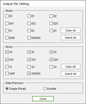
Figure 5 Output File Setting dialog box