Basic Gear Terminology
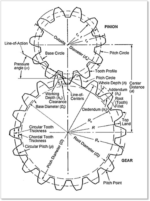
In order to use the several types of gears supported by RecurDyn, it is necessary to understand terminology and concepts associated with basic gear system. The following figure shows a graphical representation of a Spur gear and the terms which are the simplest type of gear. The calculations for spur gears also simple and they are used as the basis for the calculations for other types of gears. The following figure shows the meshing of standard spur gears which have the reference circles called Pitch Circle to contact and roll with each other.
Generally, in a gear pair, the term of PINION indicates the smaller one of the two mating gears and the term of GEAR is the larger one.
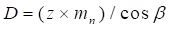
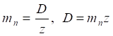
Module ( ) is the unit of size to
indicate how big a gear is. It is the ratio of Pitch Diameter (D)
of the gear divided by the number of teeth (z). Therefore, the mutual
relation between the Module and Pitch Diameter etc. is as
follows.
) is the unit of size to
indicate how big a gear is. It is the ratio of Pitch Diameter (D)
of the gear divided by the number of teeth (z). Therefore, the mutual
relation between the Module and Pitch Diameter etc. is as
follows.
Pitch Diameter (D) is the diameter of Pitch Circle which is the imaginary circle which rolls without slip, such that if a gear pair was imagined as two disks with a single point of contact, the diameter of discs would be Pitch Diameter.
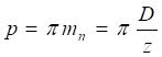
Circular Pitch (p) is the distance measured on Pitch Circle between any two similar points on adjacent teeth. It can be calculated with the number of teeth (z) and Pitch Diameter (D).
Tip Diameter or Outside Diameter is the overall diameter of the gear, Root Diameter is the diameter of a circle around the bottom (root) of the gear tooth spaces. And, Base Circle is the circle from which the involute portion of the tooth profile is generated.
Addendum is the radial distance from Pitch
Circle to the top of the gear tooth. This result can be defined as a ratio
called Addendum Factor based on the defined Module (). In the case of Spur Gear,
Addendum is equal to the value of Module () because Addendum
Factor is defined as 1 as the default setting.
Dedendum is the radial distance from Pitch Circle to the bottom of the gear tooth. It is possible to define this value as Dedendum Factor which is defined as 1.5 as the default setting.
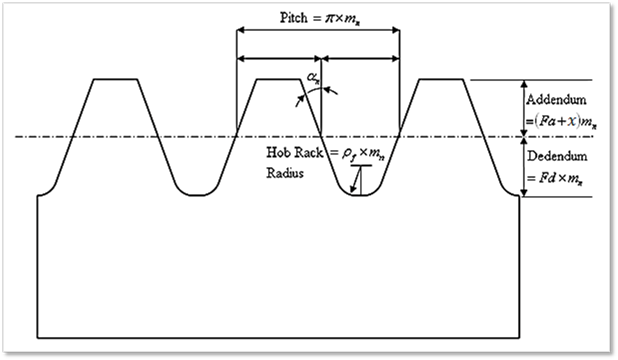
The following Figure 2 shows how to define both Addendum and Dedendum in a gear.
Figure 2 Definition of some parameters in Gear Geometry
The representation of Gear Width and Delta Tooth Thickness shows in following figures.
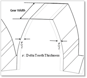
Figure 3 Definition of other parameters in a Gear Geometry
Helix Angle ( )
is the angle between the axis of a helical gear and an imaginary line tangent to
the tooth with helicoid. Lead (
)
is the angle between the axis of a helical gear and an imaginary line tangent to
the tooth with helicoid. Lead ( )
is the distance of one complete rotation as shown in Figure 4.
)
is the distance of one complete rotation as shown in Figure 4.
A pitch of a helical gear can be measured perpendicular to
teeth which is called Normal Pitch ( ), or can be measured in axial plane which
is called Transverse Pitch (
), or can be measured in axial plane which
is called Transverse Pitch ( or
or  ) as
shown below.
) as
shown below.
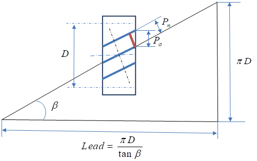
Figure 4 Helix Angle and Lead
The normal module called just Module in Helical Gear of RecurDyn/Gear has the following relation with Normal Pitch.

Calculation of Gear Dimension
In order to generate a Gear shape, it is necessary to use the following Input Parameters which are indicated in Figure 1 and Figure 2 as well as Table 1. By using them, it is possible to calculate several results related to Gear Terminology as shown Table 2.
|
Input Parameters | |
|
|
Module |
|
|
Pressure Angle |
|
|
Helix Angle |
|
|
Number of Teeth |
|
|
( Addendum Factor ) or ( Addendum Radius ) |
|
|
( Dedendum Factor ) or ( Whole Depth ) |
|
|
Hob Rack Radius Coefficient |
|
|
Addendum Modification Coefficient |
|
|
Delta Tooth Thickness |
|
|
Gear Width |
Table 1 Input Parameters
|
Calculated Results | |
|
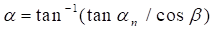
Radial Pressure Angle |
|
|
Pitch Diameter |
|
|
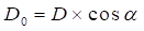
Base Diameter |
|
|
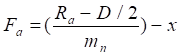
Addendum Factor |
|
|
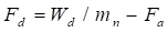
Dedendum Factor |
|
|
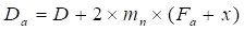
Tip(Outside) Diameter |
|
|
Root Diameter |
|
|
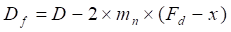
Circular Tooth Thickness |
|
|
Pitch Radius |
|
|
Tip Radius |
|
|
Base Radius |
|
|
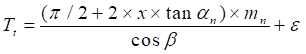
Root Radius |
|
Table 2 Calculated Results