The user can create a gear geometry by the following procedure.
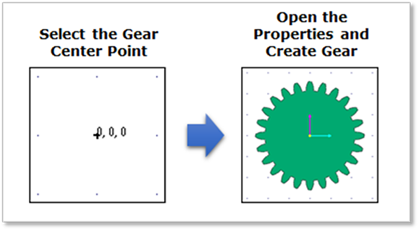
•Point, WithDialog
•Point: Selects the gear center point.
•Dialog: Displays the gear properties. For more information, refer to Geometric Entities.
•Point, Direction, WithDialog
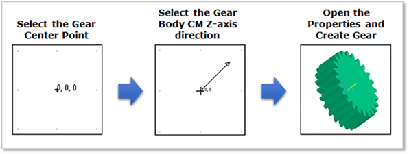
•Point: Selects the gear center point.
•Direction: Selects the center marker of gear body to Z axis based on the inertia reference frame. It becomes the rotation axis of gear body.
•WithDialog: Displays the gear properties. For more information, refer to Geometric Entities.
•Group or Body, Direction, WithDialog
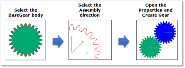
•Group or Body: Selects the creating gear and the assembling base gear.
•Direction: Selects the assembling direction to the base gear.
•Dialog: Displays the gear properties. For more information, refer to Geometric Entities.
•Group or Body, Direction, Clearance, WithDialog
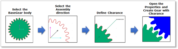
•Group or Body: Selects the creating gear and the assembling base gear.
•Direction: Selects the assembling direction to the base gear.
•Clearance: Adjusts the assembly offset when two gears are assembled.
•WithDialog: Displays the gear properties. For more information, refer to Geometric Entities.