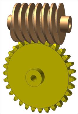
A worm gear is used for transmitting power between two non-parallel and non-intersecting shafts. It is useful when a large speed reduction ration is require between crossed axis shafts. A worm is similar to a screw and a worm gear is similar to a nut. Therefore, if the worm is rotated, the worm gear can be caused to rotate due to the screw like action of the worm.
Figure 1 Worm & Worm Gear system
Worm & worm gear are composed of a single body. Gear geometries are created from the parameters of ISO standards. The tooth profile is represented by multiple arcs. The sprocket tooth geometry data is:
•Created from a predefined data file
•Edited from a predefined data file
•Exported from a predefined data file
•Imported from a predefined data file

Figure 2 Worm icon of the Gear group in the Gear tab
Terminology
Worm tooth dimensions such as addendum, dedendum, pressure angle, etc. follows the same standards as those for Spur and Helical gears. For more information, refer to Geometric Entities. A worm is regarded as a cylinder with a ridge (V-type shape) wrapped in a spiral around it as shown below.
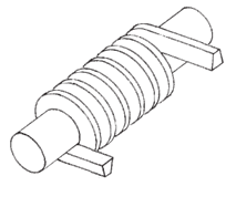
Figure 3 The way to generate a simple Worm
Therefore, a worm can be considered a cylindrical type gear with screw threads. Number of threads (n), which is called ‘Number of Stars’ in RecurDyn/Gear, in the worm is equivalent to the number of teeth in a gear of a screw type gear mesh. It can be supported form 1 to 4. The number of threads on a worm can be shown by looking at the end and counting the thread starts as shown below.
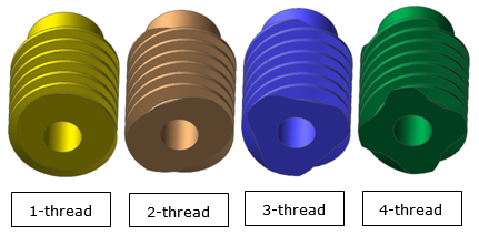
Figure 4 Number of threads of a Worm
Axial Pitch (Pa) of a worm is a distance measured along the pitch line of the gear. It can be determined by measuring the distance between any corresponding points of adjacent threads parallel to the axis. It is note that the axial pitch of a worm is equal to Circular Pitch (Pc) of the mating worm gear.
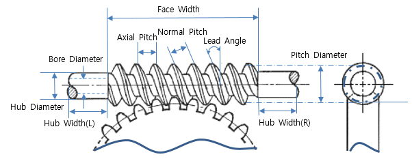
Figure 5 Worm Terminology
Lead ( ) is the linear distance
through which a point on a thread moves ahead in one revolution of the worm. For
single start threads, lead is equal to the axial pitch. Therefore, lead can be
calculated as the product of axial pitch and number of starts.
) is the linear distance
through which a point on a thread moves ahead in one revolution of the worm. For
single start threads, lead is equal to the axial pitch. Therefore, lead can be
calculated as the product of axial pitch and number of starts.

Lead Angle ( ) is the angle between the tangent
to the tread helix on the pitch cylinder and the plane normal to the axis of the
worm. If one complete turn of a worm is imagined to be unwound from the body of
the worm, it will from an inclined plane whose base is equal to the pitch
circumference of the worm and altitude is equal to lead of the worm, as shown
below. In addition, the lead angle is an important factor in determining the
efficiency of a worm and worm gear set. Therefore, the efficiency increase as
the lead angle increases.
) is the angle between the tangent
to the tread helix on the pitch cylinder and the plane normal to the axis of the
worm. If one complete turn of a worm is imagined to be unwound from the body of
the worm, it will from an inclined plane whose base is equal to the pitch
circumference of the worm and altitude is equal to lead of the worm, as shown
below. In addition, the lead angle is an important factor in determining the
efficiency of a worm and worm gear set. Therefore, the efficiency increase as
the lead angle increases.

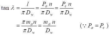
where  is Axial Module,
 is Pitch Diameter of the
worm.
is Pitch Diameter of the
worm.
Normal Pitch (Pn) of a worm is a distance measured along the normal plane which is the plane normal to the tooth surface at a pitch point and perpendicular to the pitch plane as shown in Figure 6.
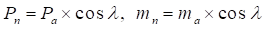
where  is Normal
Module which is called just Module in Worm and Worm
Gear of RecurDyn/Gear. This is the input value
to make them.
is Normal
Module which is called just Module in Worm and Worm
Gear of RecurDyn/Gear. This is the input value
to make them.
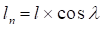
The term normal pitch is used for a worm having single start
threads. In case of a worm having multiple start threads, the term normal lead
(n) is used as
follows.
Diameter Factor (Q) means Pitch Diameter of worm (Dw) over axial module (ma). It is effective to use this factor when defining a Worm Gear meshing user-defined Worm because the Number of Start option in the worm dialog box doesn’t work if Lead Angle is selected.

For more information, refer to Geometric Entities