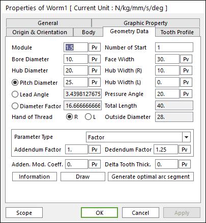
Figure 1 Worm property page [Geometry Data page]
The Worm property page is shown in Figure 1. The parameters are explained below.
•Module: Enters the module of the gear.
•Number of Start: Enters the number of threads on the worm. For more information, click here.
•Bore Diameter: Enters the bore diameter of the worm.
•Face Width: Enters the face width of the worm.
•Hub Diameter: Enters the hub diameter of the worm.
•Hub Width (R): Enters the hub width for the right of the worm.
•Hub Width (L): Enters the hub width for the left of the worm.
•Pressure Angle: Enters the pressure angle of the gear.
•Total Length: Shows the total length of the worm.
•Pitch Diameter: Enters the pitch diameter of the worm. This can define a lead angle. For more information, click here.
•Lead Angle: Enters the lead angle of the worm. This can define a pitch diameter. For more information, click here.
•Diameter Factor: Enter the factor for Pitch Diameter. This can define a pitch diameter and lead angle. For more information, click here.
•Hand of Thread: Defines the direction of thread as L or R.
•Outside Diameter: Shows the outside diameter of the worm.
•Parameter Type: two methods are supported to define the Addendum and Dedendum.
•Factor: Defines the addendum and dedendum as factors. For more information, click here.
o Addendum Factor: Enters the factor to define the addendum.
o Dedendum Factor: Enters the factor to define the dedendum.
•Addendum Radius & Whole Depth: Defines the addendum and dedendum as addendum radius and whole depth. For more information, click here.
o Addendum Radius: Enters the addendum radius for the gear.
o Whole Depth: Enters the whole depth as summation for the addendum and dedendum.
•Adden. Mod. Coeff.: Enters the coefficient to define the addendum.
•Delta Tooth Thick.: Enters the delta value to define the tooth thickness. For more information, click here.
•Information: Shows the calculated values for Pitch Diameter, Outside Diameter, Root Diameter, and Tooth Thickness.
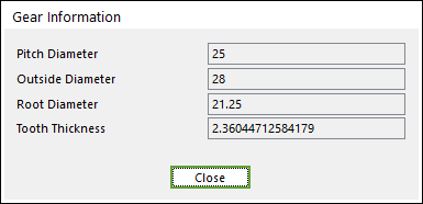
Figure 2 Gear Information dialog box
•Draw: All data must be defined with respect to the tooth marker. You can move points graphically by using the mouse directly. Also, the tooth profile can be modified in Tooth Profile page.
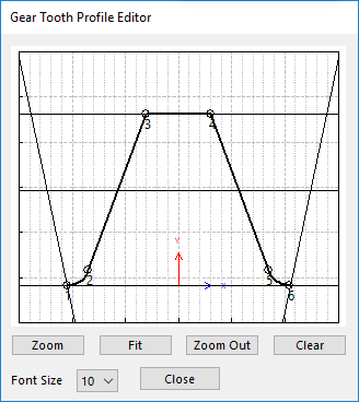
Figure 3 Gear Tooth Profile Editor dialog box
•Generate optimal arc segment: In order to apply the modification of tooth, this button should be clicked.