A bevel gear is used to transmit power between two intersecting shafts at any angle. It is classified as Straight, Spiral, and Zerol according to checking the Spiral Angle and Cutter Radius option. Straight bevel gears are the simplest form which has straight and tapered teeth. Spiral bevel gears have curved oblique teeth on which contact starts at one end of the tooth and progresses smoothly to the other end. And then, Spiral bevel gears have two or more teeth in contact at all times such that they transmit motion more smoothly and quietly than Straight bevel gears. Finally, Zerol bevel gears are similar to Spiral bevel gear, but it has been defined the spiral angle as zero at the middle of the face width. Therefore, the direction of the curved teeth of it is the same general direction as Straight bevel gears.
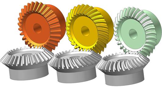
The following figure shows three types of bevel gears generated in RecurDyn/Gear.
Figure 1 Types of Bevel Gears (Straight, Spiral, Zerol)
A bevel gear is composed of a single body. Gear geometries are created from the parameters of ISO standards. The tooth profile is represented by multiple arcs. The sprocket tooth geometry data is:
•Created from a predefined data file
•Edited from a predefined data file
•Exported from a predefined data file
•Imported from a predefined data file
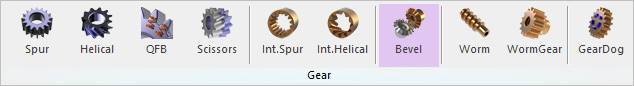
Figure 2 Bevel icon of the Gear group in the Gear tab
Terminology
Bear gear teeth are proportioned in accordance with the standard system of tooth proportion s used for spur gears. However, because bevel gear teeth are tapered and the narrow end of the teeth vanishes at the center of gear geometry, the reference of important parameter dimension is the outer end as shown Figure 3.
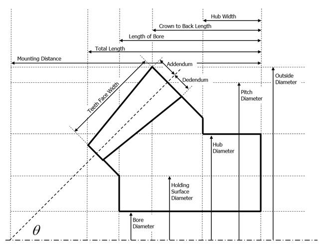
Figure 3 Bevel Gear Geometry
For more information, refer to Geometric Entities