A worm gear is used for transmitting power between two non-parallel and non-intersecting shafts. It is useful when a large speed reduction ration is required between crossed axis shafts. A worm is similar to a screw and a worm gear is similar to a nut. Therefore, if the worm is rotated, the worm gear can be caused to rotate due to the screw like action of the worm.
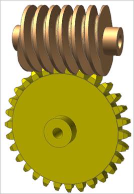
Figure 1 Worm & Worm Gear system
Worm & worm gear are composed of a single body. Gear geometries are created from the parameters of ISO standards. The tooth profile is represented by multiple arcs. The sprocket tooth geometry data is:
•Created from a predefined data file
•Edited from a predefined data file
•Exported from a predefined data file
•Imported from a predefined data file

Figure 2 WormGear icon of the Gear group in the Gear tab
Terminology
Worm Gear has a pitch diameter at the center point of the wrap-around curve. It has parts similar to a spur gear except for one, which is called Throat Diameter as shown in Figure 8. And Pitch Diameter is calculated the same as for spur gears.
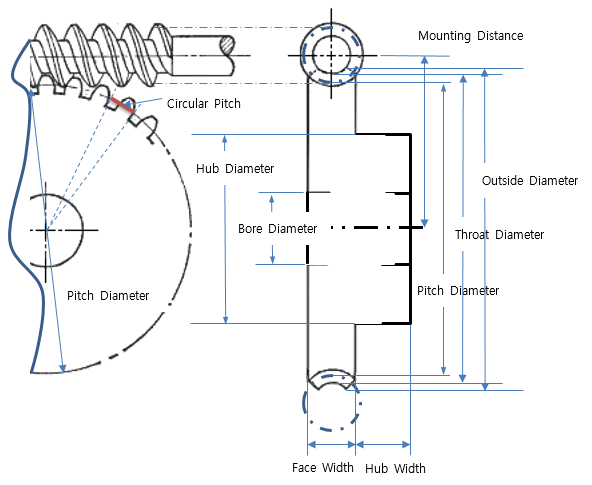
Figure 3 Worm Gear Terminology
Circular Pitch (Pc) of a worm gear is a distance measured along the pitch circle of the gear. It can be determined by measuring the distance between any two corresponding points of adjacent teeth as shown above. In order to calculate this parameter, the axial module (ma) should be used, which can be calculated as the following relation. For reference, the normal module (mn) is the input value in the module of worm dialog box.

Throat Diameter (Dt) has the following relation with Pitch Diameter (D) and Addendum.

Pitch Diameter (D) has the following relation with Normal Module (mn), the number of teeth (z) and Lead Angle (γ).

Addendum has the following relation with Addendum Factor (Fa) and Addendum Modification Coefficient (x)

For more information, refer to Geometric Entities