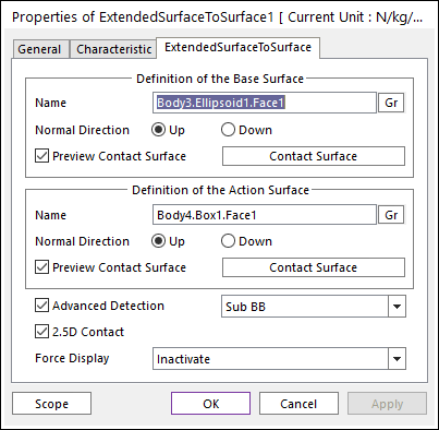
Figure 1 Properties of ExtendedSurfaceToSurface dialog box
•Definition of The Base Surface
•Entity Name: Defines the name of base surface. The base surface can be dispatched from the Working Window by clicking Gr.

Figure 2 Preview of the normal directions, contact patches and boundary box
•Normal Direction: Defines the normal direction of base surface for a contact as shown in Figure 2. For more information, click here.
•Preview Contact Surface: If this option is checked, the patches making the contact surface and its boundary box are shown on the Working Window as shown.
•Contact Surface: Accesses the Surface Patch dialog box as shown Figure 3.
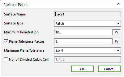
Figure 3 Surface Patch dialog box
o Surface Type: Select the Patch or Surface type for a contact surface.
Patch: If the user selects the Patch type, the contact surface is approximated to multiple patches.
Surface: If the user selects the Surface type, the contact surface is fitted to a parameterized surface. If a contact geometry has a curvature and the user want to get a smooth contact force, the Surface type should be selected. Note that the Advanced Detection option should be activated before using the Surface type.
o Max Penetration: Select the maximum penetration. If the penetration is greater than this value, the contact force is not generated. A good guideline is to set it at 3-10 times the expected penetration.
o Plane Tolerance Factor: Specifies the surface tolerance factor as a value from 0 to 10. A smaller value produces a more refined patch. For more information, click here.
o Minimum Plane Tolerance: If the decreasing plane tolerance factor has no effect on the patch refinement, the user should decrease the minimum plane tolerance. For very small surfaces (such as 1mm*1mm size), the user may need to decrease minimum plane tolerance to get an effective patch. Note that the default value of the minimum plane tolerance is 1.e-5.
o No. of Divided Cubic Cell: Shows the number of cubic cells dividing a contact boundary box in each direction. This value is automatically calculated, but can be modified by the user.
•Definition of The Action Surface
•Entity Name: Defines the name of action surface. The action surface can be dispatched from the Working Window by clicking Gr.
•Normal Direction: Defines the normal direction of an action surface for a contact as shown in Figure 2. For more information, click here.
•Preview Contact Surface: If this option is checked, the patches making the contact surface and its boundary box are shown on the Working Window as shown.
•Contact Surface: Accesses the Contact Surface dialog box as shown Figure 3. For more information, click here.
•Advanced Detection: Select an advanced detection type as Full or Sub BB.
•Full: All action contact patches are examined for a contact analysis.
•Sub BB: The action surface is divided some sectors as shown in Figure 4 and the sub sectors are firstly examined whether the action surface interferes with the base surface. If the contact is expected, all patches that belong to the sub sector are examined.

Figure 4 Advanced detection with the Sub BB type
•2.5D Contact: The option decides the surface equation of 2.5D Contact.
•If this option is not checked, the surface is using the polynomial equation (RecurDyn 6.2).
•If this option is checked, the surface is using the Hermitian polynomial (RecurDyn 6.21). The default is checked.
•Force Display: Graphically displays the resultant force vector on the view window. For more information, click here.