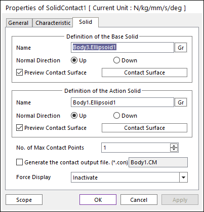

Figure 1 Properties of Solid dialog box
•Definition of the Base Solid
•Entity Name: Defines the name of base solid (or available surface). The base solid (or available surface) can be dispatched from the Working Window by clicking Gr.
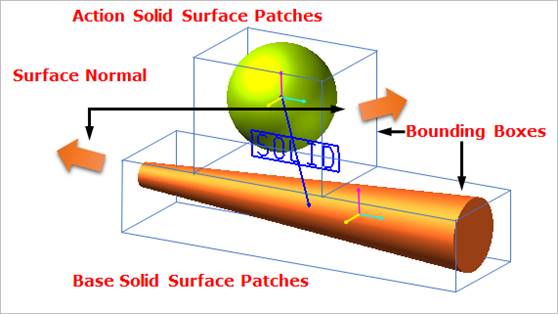
Figure 2 Preview of the normal directions, contact patches and nodes
•Normal Direction: Defines the normal direction of a base solid (or an available surface) for a contact as shown in the above figure.
o The contact is available in the specified direction.
o As selecting “Up” or “Down”, the user can change the contact direction of a base surface.
o If this page is activated, the normal direction is automatically shown on the Working Window.
•Preview Contact Surface: If this option is checked, the patches making the contact surface are shown on the Working Window as shown in the above figure.
•Contact Surface: Accesses the Solid Patch dialog box as shown in the below figure.
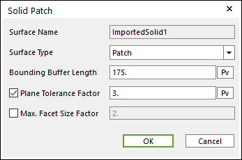
Figure 3 Solid Patch
dialog box
o Surface Type: Select only the Patch type for a contact surface. In the Patch type, the contact surface is approximated to multiple triangular patches.
o Bounding Buffer Length: Before calculating the collision detection, contact pre-search are performed with base and action bounding box. The bounding buffer length defines the offset length of bounding box compared to the real bounding box as shown in Figure 4.
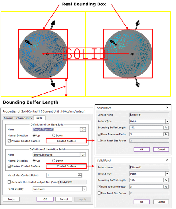
Figure 4 Definition of Bounding Buffer Length
o Plane Tolerance Factor: Specifies the surface tolerance factor as a value from 0 to 10. A smaller value produces a more refined patch. For more information, click here.
o Max. Facet Size Factor: Specifies the max. facet size factor as a value from 0 to 10. This value controls the maximum size of triangular patch length. Even though box geometry, if this value is defined (checked), box geometry can be used with lots of triangular patches as shown in Figure 5.
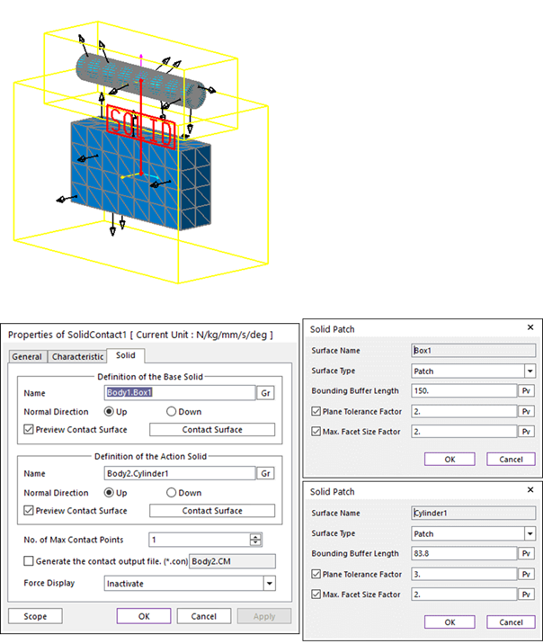
Figure 5 Example of Plane Tolerance Factor and Max. Facet Size Factor
•Definition of The Action Solid
•Entity Name: Defines the name of action surface. The action surface can be dispatched from the Working Window by clicking Gr.
•Normal Direction: Defines the normal direction of an action surface for a contact. For more information, click here.
•Preview Contact Surface: If this option is checked, the nodes making the contact surface are shown on the Working Window.
•Contact Surface: Accesses the Solid Patch dialog box. For more information, click here.
•No. of Max Contact Point: Defines the number of max contact point.
•Generate the contact output file(*.con): When user checks the “Generate the contact output file” option, RecurDyn creates the contact output file based on the contact output reference marker which can be defined in the contact force page. The user can calculate the local contact information based on the contact output reference by using *.con output file'. Then Recurdyn/Solver reports all contact-related information to the text file. The format is as follows:
|
Col. |
Variables |
Descriptions |
|
1 |
Time |
Simulation Time |
|
2 |
NCP |
Total number of calculated contact points |
|
3 |
NO |
Current contact point number |
|
4 |
X_RefPos |
Position X of Output Reference Marker from Global |
|
5 |
Y_RefPos |
Position Y of Output Reference Marker from Global |
|
6 |
Z_RefPos |
Position Z of Output Reference Marker from Global |
|
7 |
Z_EulerA |
Z Euler Angle of Output Reference Marker from Global |
|
8 |
X_EulerA |
X Euler Angle of Output Reference Marker from Global |
|
9 |
Z_EulerA |
Z Euler Angle of Output Reference Marker from Global |
|
10 |
X_ConPos |
Position X of Calculated Contact Reference Frame from Global |
|
11 |
Y_ConPos |
Position Y of Calculated Contact Reference Frame from Global |
|
12 |
Z_ConPos |
Position Z of Calculated Contact Reference Frame from Global |
|
13 |
X_NorDir |
Normal Direction X of Calculated Contact Reference Frame from Global |
|
14 |
Y_NorDir |
Normal Direction Y of Calculated Contact Reference Frame from Global |
|
15 |
Z_NorDir |
Normal Direction Z of Calculated Contact Reference Frame from Global |
|
16 |
X_TanDir |
Tangent(Friction) Direction X of Calculated Contact Reference Frame from Global |
|
17 |
Y_TanDir |
Tangent(Friction) Direction Y of Calculated Contact Reference Frame from Global |
|
18 |
Z_TanDir |
Tangent(Friction) Direction Z of Calculated Contact Reference Frame from Global |
|
19 |
Pen |
Penetration Depth |
|
20 |
PenVel |
Penetration Depth Velocity or Relative Velocity in Normal Direction |
|
21 |
TanVel |
Relative Velocity in Tangent Direction |
|
22 |
FricCoeff |
Friction Coefficient |
|
23 |
NorForce |
Normal Force Magnitude |
|
24 |
FricForce |
Friction Force Magnitude |
•Force Display: Graphically displays the resultant force vector on the view window. For more information, click here.