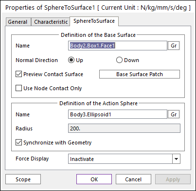
Figure 1 Properties of SphereToSurface dialog box
•Definition of The Base Surface
•Entity Name: Defines the name of base surface. The base surface can be dispatched from the Working Window by clicking Gr.

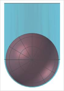
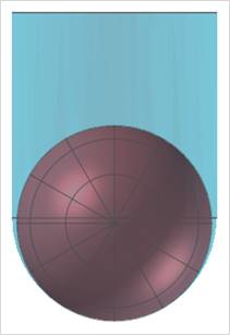
Figure 2 Preview of the normal direction and contact patches
•Normal Direction: Defines the normal direction of a base surface for a contact as shown in Figure 2. For more information, click here.
•Preview Contact Surface: If this option is checked, the patches making the contact surface are shown on the Working Window.
•Base Surface Patch: Accesses the Base Surface Patch dialog box as shown in Figure 3.
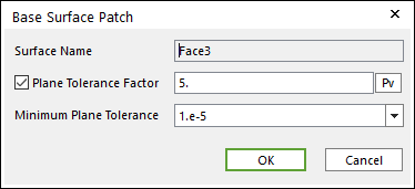
Figure 3 Base Surface Patch dialog box
o Plane Tolerance Factor: The error tolerance of contact surface relative to a real surface as shown in Figure 4. The user can specify the surface tolerance factor as a value from 0 to 10. If the factor is closer to 0, the number of triangular patches will be increased. And if the factor is closer to 10, the number of triangular patches will be decrease.

Figure 4 Error tolerance of a contact surface
o Minimum Plane Tolerance: While using extended surface to surface contact, to make refined patch, decrease plane tolerance factor. If the decreasing plane tolerance factor has no effect on patch, decrease minimum plane tolerance. For very small geometries such as 1mm * 1mm size, maybe they need to decrease minimum plane tolerance to get effective patch. The default value of minimum plane tolerance is 1.e-5.
•Use Node Contact Only: Nodes of contact surface are used to generate the contact force of sphere to surface contact. Generally, this option can be very useful for accuracy and solving speed when the triangular patch size ( or line length of triangular patch ) is much smaller than sphere size (or radius).
o If the user does not use this option, the contact is applied as patch shape only.
o If the user uses this option, the contact is applied as flexible body shape more correctly.
•Definition of The Action Sphere
•Entity Name: Defines the name of action sphere. The action sphere can be dispatched from the Working Window by clicking Gr.
•Radius: Shows the radius of base sphere. This value is automatically determined by the radius of the action geometry but if the user doesn’t check the Synchronize with Geometry option, the user can directly input the radius or change it as the parametric value by clicking PV.
•Synchronize with Geometry
o If this option is checked, Radius in contact properties is automatically defined with that of the specified graphic.
o If this option is not checked, the user can modify the contact properties.
•Force Display: Graphically displays the resultant force vector on the view window. For more information, click here.