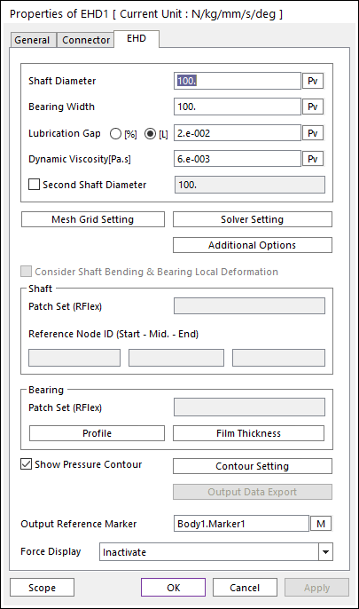
The user can modify the property of EHD Rotational Lubrication in the following dialog box.
Figure 1 EHD Rotational Lubrication property page [EHD page]
•Shaft Diameter: Defines a shaft diameter of EHD Rotational Lubrication.
•Bearing Width: Defines a bearing width of EHD Rotational Lubrication.
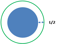
•Lubrication Gap: Defines a characteristic of EHD.
•[%]: Defines this value using the percentage method.
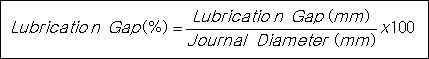
Eq.1 Equation of Lubrication Gap
•[L]: Defines this value as length unit.
•Dynamic Viscosity [Pa.s]: Defines lubricant viscosity.
•Second Shaft Diameter: If this option is defined, it is possible to make the cone shape shaft.
•Mesh Grid Setting: Defines mesh grids for Oil Hole and Groove Effects. For more information, click here.
•Additional Options: Defines viscosity information, boundary pressure and asperity contact information. Also, Flexible effect can be given. For more information, click here.
•Solver Setting: Defines parameters related to EHD Pressure Convergence. In the case of RDEHD, this function is activated. For more information, click here.
•Consider Shaft Bending & Bearing Local Deformation: If this option is checked, RecurDyn solver compute bending shape of shaft based on reference nodes of it and local deformation of bearing. And then, RecurDyn solver reflects on this effect in order to compute local film thickness and evaluate hydrodynamic pressure.
•Shaft: User have to set RFlex patch to defined lubrication region of shaft. And then, user have to 3 reference nodes in order to compute bending shape of shaft. We recommend that 3 Reference nodes are located on the both end and middle position of shaft.
•Patch Set(RFlex): Selects a patch set in which lubrication region of shaft is defined.
•Reference Node ID(Start- Mid. - End): Select a reference nodes which is used for base nodes in order to define bending shape of shaft. We recommend that start node is located at the end of the negative z direction of action marker and end node is located at the end of the positive z direction of action marker. In the case of middle node, it is recommended that middle node is located at the same position of action marker.
•Bearing: User have to set RFlex patch to define lubrication region of bearing. And then, 1 reference node should be defined. It is used for reference frame in order to define bearing local deformation for nodes in lubrication region.
•Patch Set(RFlex): Selects a patch set in which lubrication region of bearing is defined.
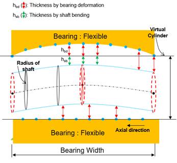
Figure 2 Schematic diagram of shaft bending and bearing local deformation of nodes in lubrication region.
•Profile: Defines a offset data in angle and height coordinate. User can apply arbitrary cylinder shape to EHD analysis by setting this offset table data.
•Film Thickness: Define oil film thickness by boundary condition.
•Show Pressure Contour Animation: If this option is checked, the user can see the EHD contour during the playing animation.
•Contour Setting: Defines the EHD Contour information. For more information, click here.
•Output Data Export: Displays on Scope or exports for the film thickness and file pressure. For more information, click here.
•Output Reference Marker: Selects a reference marker for EHD force result. The default marker is a base marker of EHD.
•Force Display: The user can graphically display the resultant force vector on the Working Window.
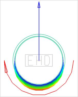
Figure 3 Force Display of EHD Rotational Lubrication