The user can control mesh numbers and Oil Hole & Groove Effects.
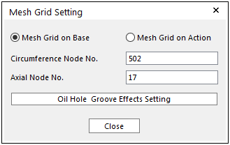
Figure 1 Mesh Grid Setting dialog box
•Mesh Grid on Base (default): Mesh grid are distributed on the inner surface of base body (outer body).
•Mesh Grid on Action: Mesh grid are distributed on the outer surface of action body (inner body).
•Axial Node No.: “M”
•Circumference Node No.: “N”
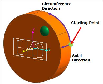
Figure 2 Defining Circumference Node No. and Axial Node No.
•Oil Hole & Groove Effects Setting
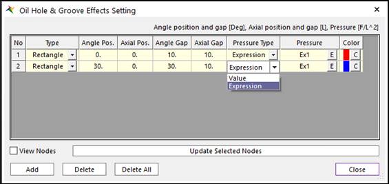
Figure 3 Oil Hole & Groove Effects Setting dialog box
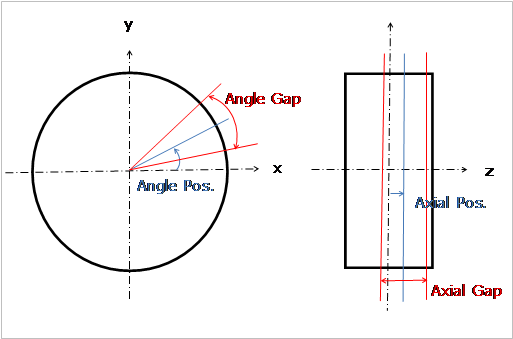
Figure 4 Defining Oil hole and Groove region
•Type: Defines a shape of oil hole and groove effects.
•Angle Pos.: Defines a center position of the angle.
•Axial Pos.: Defined a center position of the axial.
•Angle Gap: Defines a gap of the angle.
•Axial Gap: Defines a gap of the axial.
•Pressure Type: Define pressure value on oil hole and groove region with constant value or time dependent expression.
•Pressure: Defines the pressure value.
•Color: Displays the selected nodes as this color if the user checks View Nodes.
•View Nodes: Shows the selected nodes in the Working Window.
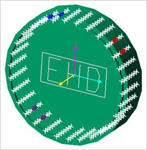
Figure 5 View Nodes
•Update Selected Nodes: The position of Oil Hole and Groove is changed.