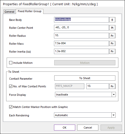
The user can modify the properties of fixed roller in the following dialog box.

Figure 1 FixedRollerGroup property page
•Base Body: Defines the base body of revolute joint.
•Roller Center Point: Defines the center point of fixed roller body.
•Roller Radius: Defines the radius of fixed roller.
•Roller Mass: Defines the mass of the fixed roller.
•Roller Inertia (Izz): Defines the mass moment of inertia with respect to the z-axis of the center marker of the roller.
•Include Motion: Defines the angular motion of the fixed roller. The user can define the roller displacement, velocity and acceleration by using the Function Expression. Refer to Motion.
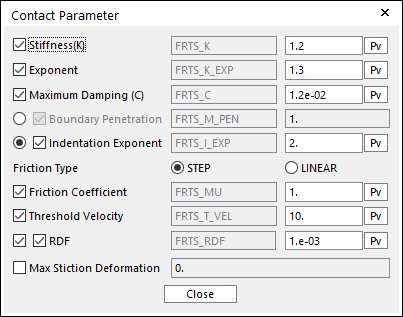
•Contact Parameter: Allows the user to modify contact parameters by clicking To Sheet. In this dialog box, the user can modify the contact parameters of contact forces applied between the sheet and the fixed roller. Refer to the Contact Formulus for MTT2D.

Figure 2 Contact Parameter dialog box
•No. of Max Contact Points: Defines the number of max contact point for output. User can define this value from 1 to 5000. This value only affects Force Display and RPLT data about the contact points. The default value is 10.
•Force Display: Graphically displays the all contact force vectors (the sum of the normal and tangential contact force) at each contact point up to the “No. of Max Contact Point”.
•Match Center Marker Position with Graphic: If this is checked, the position of center marker of fixed roller body is always matched with the center of roller geometry.
•Each Rendering: The selected mode can be displayed in Each Render mode. For more information, click here.