Contact Formulas
In a field of multi-body dynamics, one of the most well-known approximations of the dynamic behavior of a contact pair is that:
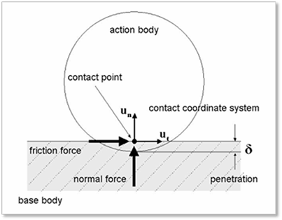
•One body penetrates the other body with a velocity on a contact point.
•The contact normal and friction forces are generated between a contact pair, shown in Figure 1.
Figure 1 Contact forces between a contact pair
The contact normal force is defined as a function of the penetration as follows.
 (1)
(1)
where,  and
and  are the amount of
penetration and its velocity, respectively. The stiffness and damping
coefficients of k and c can be determined from an experimental
method. But the above equation (1) has often been different from a physical
phenomenon. Many people have studied potential solutions the contact problem,
and some reasonable solutions have been proposed. In this toolkit, two of them
are implemented for the contact normal force as shown in the following
equation.
are the amount of
penetration and its velocity, respectively. The stiffness and damping
coefficients of k and c can be determined from an experimental
method. But the above equation (1) has often been different from a physical
phenomenon. Many people have studied potential solutions the contact problem,
and some reasonable solutions have been proposed. In this toolkit, two of them
are implemented for the contact normal force as shown in the following
equation.
 (2)
(2)
 (3)
(3)
 (4)
(4)
where, the order of m can represent the
non-linearity of a spring force of restitution. The term of  can prevent a damping force from
assuming an excessive magnitude when the penetration is very small. The exponent
n yields an indentation damping effect. When the penetration is very small,
the contact force may be negative due to a negative damping force from Eq. (1),
which is not realistic. This situation can be overcome by using the indentation
exponent greater than one, according to Eq. (3). The equation (4) determines the
damping coefficient with a step function as shown in Figure 2. The
can prevent a damping force from
assuming an excessive magnitude when the penetration is very small. The exponent
n yields an indentation damping effect. When the penetration is very small,
the contact force may be negative due to a negative damping force from Eq. (1),
which is not realistic. This situation can be overcome by using the indentation
exponent greater than one, according to Eq. (3). The equation (4) determines the
damping coefficient with a step function as shown in Figure 2. The  is a
boundary penetration.
is a
boundary penetration.
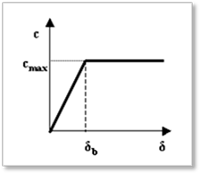
Figure 2 Boundary penetration and damping coefficient
A friction force can be determined as follows.
 (5)
(5)
where,  and
and  are a contact
normal force and a friction coefficient, respectively. Using the tangential
velocity of
are a contact
normal force and a friction coefficient, respectively. Using the tangential
velocity of  , the friction coefficient of
  is
determined as shown in Figure 3.
is
determined as shown in Figure 3.
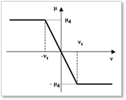
Figure 3 Relationship between a friction coefficient and a relative velocity
A friction coefficient is determined relatively to a tangential relative velocity at a contact point. In this time, two interpolation methods can be used. One is STEP function and the other is LINEAR function as shown in Figure 4. Note, flexible roller contact uses the different friction force like that Figure 5.
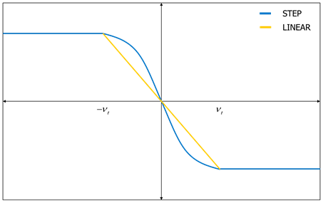
Figure 4 Friction forces generated by step and linear function
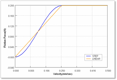
Figure 5 Friction forces generated by step and linear function in Flexible Roller
Max Stiction Deformation controls the stick-slip effect on the sheet to roller contact. The default is unchecked, and the value is zero. Also, the value must be greater than or equal to zero. If the tangential velocity is smaller than the threshold velocity, then the stick effect can be occurred. On the other hand, if the tangential velocity is greater than the threshold velocity, then the friction model is on the slip condition.
RDF(Rebound Damping Factor) controls the rebound damping force when bodies are on restitution phase. Default is checked, and the value is 0.001. To see about the RDF, click here.

Figure 6 Effect of the RDF (Rebound Damping Factor)