This page defines characteristic values to contact between two geometry entities. Solid Contact entity is using this page.
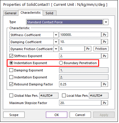
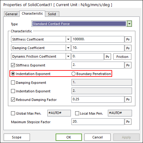
Figure 1 Solid Contact property page [Standard Contact Force]
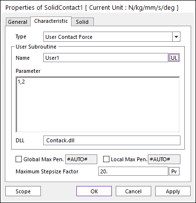
Figure 2 Solid Contact property page [User Contact Force]
•Type: Select a type as Standard Contact Force or User Contact Force.
•Standard Contact Force: Defines the contact properties.
•User Contact Force: Defines by the user written contact subroutine (Refer Contact User Subroutine).
•Global Max Penetration: Specifies the maximum penetration depth. This value must be greater than local max penetration. Refer to Modification Rules for the Solid Contact – Detailed Contact Options.
•If this option is checked (Manual Mode), user must input the appropriate global maximum penetration manually.
•If this option is not checked (Automatic Mode), the solid contact finds the global maximum penetration automatically during the simulation. (The default is unchecked.)
•Local Max Penetration: Specifies the calculation method of penetration depth. If the real penetration depth is between zero and this value, RecurDyn calculates the penetration depth with patch to patch approach (local PD calculation approach) and if the real penetration depth is greater than this value, RecurDyn calculates the penetration depth with global PD calculation approach. Refer to Modification Rules for the Solid Contact – Detailed Contact Options.
•If this option is checked (Manual Mode), user must input the appropriate local maximum penetration manually.
•If this option is not checked (Automatic Mode), the solid contact finds the local maximum penetration automatically during the simulation.
•Maximum Step size Factor: The maximum step size is reduced by a factor of maximum step size factor.
Standard Contact Force
•Characteristic: Defines the contact properties such as the stiffness coefficient, damping coefficient, and friction coefficients. Also, these coefficients can be given as user-defined spline curves.
•Stiffness Coefficient: Specifies a stiffness coefficient for the contact normal force.
•Stiffness Spline: The spline shows the contact normal force for the penetration. For more information, refer to click here.
•Damping Coefficient: Specifies a viscous damping coefficient for the contact normal force.
•Damping Spline: The spline shows the contact normal force for the velocity of penetration. For more information, refer to click here.
•Dynamic Friction Coefficient: Specifies a dynamic friction coefficient for the contact friction force. It has three options.
o Dynamic Friction Coefficient: The constant friction coefficient is applied.
o Friction Force Spline: The spline shows the fiction force for the relative velocity. It is recommended to use the spline that x and y values are defined as positive.
o Friction Coefficient Spline: The spline shows the friction coefficient for the relative velocity.
•Friction: Specifies some friction coefficients for the contact friction force. The friction force calculation is same with the RecurDyn general contact characteristic page. Refer to Friction.
•Stiffness and Damping Exponent: Generates a non-linear contact normal force.
•Indentation Exponent: Yields an indentation damping effect. When the penetration is very small, the contact force may be negative due to a negative damping force, which is not realistic. This situation can be overcome by using the indentation exponent greater than one.
•Boundary Penetration: Specifies a full damping penetration. If the penetration is less than this value, the damping coefficient will be calculated with the STEP function. And if the penetration is equal or greater than this value, RecurDyn uses the user–defined damping coefficient.

Figure 3 Damping Coefficient in the case of Boundary Penetration
•Rebound Damping Factor: To obtain realistic hysteric loop for energy dissipation during the contact, this rebound damping factor controls the rebound damping force when bodies are on restitution phase.

Figure 4 The hysteric loop and rebound damping factor
The contact normal force is calculated by
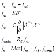
Where, K and C
are the spring and damping coefficients which are determined by an experimental
method, respectively. The m1, m2, and m3 are the stiffness, damping and
indentation exponents.  and
and  are a penetration and time
differentiation of the penetration, respectively. Rdf is the rebound damping
factor.
are a penetration and time
differentiation of the penetration, respectively. Rdf is the rebound damping
factor.
User Contact Force
•User Subroutine
•Name: Shows the name of user specified subroutine.
•Parameter: Shows the parameters used in the user specified subroutine.
•DLL: Shows the name of which DLL contains the Contact User Subroutine.