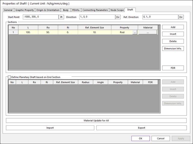
The Shaft property page is shown in Figure 1. And its parameters are explained below. The user can modify properties for the shaft such as shaft shape information. The pages such as Body, FEInfo., Connecting Parameters and Node Scope are same with fflex body. The general pages such as General, Graphic Property, Origin & Orientation are same with general body.
Figure 1 Shaft property page [Shaft page]
•Start Point: Defines a start point of the shaft.
•Direction: Defines a direction of the shaft.
•Ref. Direction: Defines a normal direction of the shaft.
•Sections: Defines each section.
•Length(L): Section length
•Outer Radius (Ro): Section outer radius
•Inner Radius (Ri): Section inner radius
•Element Size: this value is the size of uniformly dividing Length. When dividing, if there is remainder, increase the number of elements one more for each section.
•Property: Support two type as Rod, Tube. Rod if inner radius is zero, Tube type otherwise. For more information, click here.
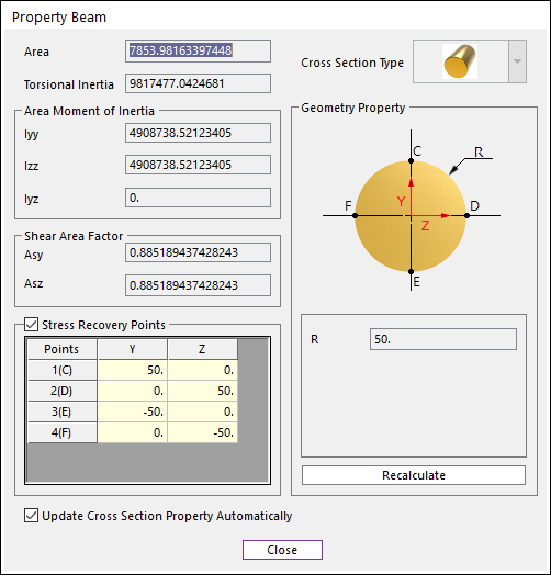
Figure 2 Property dialog for each section.
•Material: Defindes material information for each section. Material type is a linear isotropic. For more information, click here.
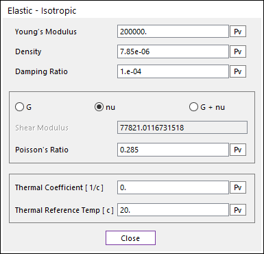
Figure 3 Material dialog for each section.
•FDR: For all general sections, this function is responsible for bearing and gear to define FDR in the connecting part.
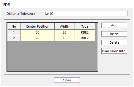
Figure 4 FDR dialog for all general sections.
o Distance Tolerance: This tolerance is used when assigning master and slave node of FDR to existing shaft.
If the distance between the newly added node (master or slave node) of FDR and the existing node is smaller than this tolerance, use the existing node, not new node for FDR.
o Center Position: Define position of master node.
o Width: Define position of two slave nodes.
o Type: Only support RBE2 type.
o Dimension Info. : Discribe FDR creation method.
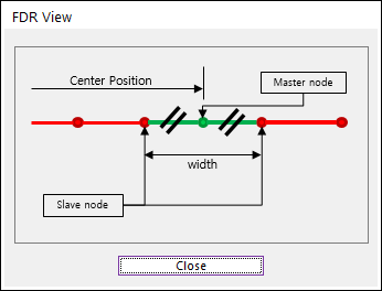
Figure 5 Dimension info. of FDR dialog.
•Define Planetary Shaft based on End Section: If this function is checked, user can create an additional shaft for plnanetary gears at the end of general sections.
•Length(L): refer. to general section.
•Outer Radius(Ro): refer. to general section.
•Inner Radius(Ri): refer. to general section.
•Element Size: refer. to general section.
•Radius: To define start position of coaxial section, distance from the center of last general section.
•Angle: To define start position of coaxial section, angle from axis of last general section.
•Property: refers to general section.
•Material: refers to general section.
•FDR: refers to general section.
•Dimension Info.: Discribe coaxial creation method.
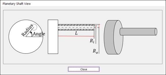
Figure 6 Dimension info. about Planetary Shaft View.
•Material update for All: If this function is used, user can chage material information through general and coaxial section.
•Import: Imports section information as XML format.
•Export: Exports section information as XML format.