It is a specialized scoping function.
•In the general body, you can scope a body result with the Scope button in the general page.
•However, the FFlex body that is consisted of many nodes requires a special function to scope nodal results.
•With the node scope function, the user can easily scope the result of nodes that are in a FFlex body.

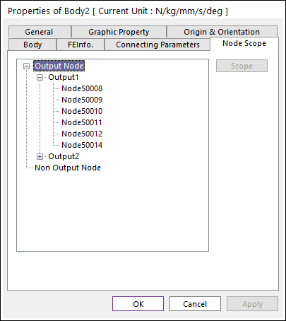
Figure 1 Node Scope tab of the Properties of FFlex Body dialog box
Output Node
A list for predefined output nodes is shown. RAD(or RAN) and RPLT files should be generated to use this function.
Non Output Node
Scope Entity can be used for nodes that are not defined as Output Node. The data can be gotten from output files of FFlex. So, it is unnecessary to simulate again. RAD(or RAN), RFA, ERD, and SRD files should be generated to use this function.
•If using non-output node, Velocity and Acceleration components are not shown.
•In order to see strain and stress results, all components regarding strain and stress should be checked in Output File Setting.
Scope
For more information, refer to Scope to understand Scope Entity dialog box.

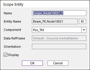
Figure 2 Scope Entity dialog box
•Name: Specifies the name of the output scope.
•Entity Name: Shows the node ID and name of a FFlex body. In non-output node case, a node can be selected.
•Component: Selects a component in the following list. In non-output node case, velocity and acceleration term are not displayed.
•Pos_TM: Magnitude of the position vector
•Pos_TX, Pos_TY, Pos_TZ: Position vector with respect to the inertia reference frame.
•Pos_PSI, Pos_THETA, Pos_PHI: Euler angle 313 with respect to the inertia reference frame.
•Vel_TM: Magnitude of velocity vector
•Vel_TX, Vel_TY, Vel_TZ: Velocity vector with respect to the reference frame of FFlex body.
•Vel_RM: Magnitude of angular velocity vector
•Vel_RX, Vel_RY, Vel_RZ: Angular velocity vector with respect to the reference frame of FFlex body.
•Acc_TM: Magnitude of acceleration vector
•Acc_TX, Acc_TY, Acc_TZ: Acceleration vector with respect to the reference frame of FFlex body.
•EX, EY, EZ, EXY, EYZ, EZX: Strain tensor component with respect to the inertia reference frame. (The shear strain is defined to an engineering shear strain.)
•E1, E2, E3: Principal strain
•EINT: Intensity strain
•EMISES: Von-mises strain
•SX, SY, SZ, SXY, SYZ, SZX: Stress tensor component with respect to the inertia reference frame.
•S1, S2, S3: Principal stress
•SINT: Intensity stress
•SMISES: Von-mises stress
•Data RefFrame: It shows what entity is used for reference frame of selected data component. Most data component use the Ground.InertiaMarker for reference frame, but data component of connector use other entities because it’s easier to analysis the data.
•Orientation: Selects a marker. This option is only supported by the Stress component and the Strain component.