The Base Marker defines the location and orientation of the joint. When the joint is created the Base Marker and Action Marker are typically defined in the same position and orientation. If one of the bodies is later moved, the two markers may not coincide. At the beginning of the simulation all the joint constraints must be satisfied, therefore the Action Body will be moved such that the all specified degrees of freedom for the joint are satisfied and the Base Marker and the Action Marker are brought together. In the case of open degrees of freedom, such as the rotational degree of freedom of a revolute joint or the sliding degree of freedom of a translational joint, there are no constraints to be satisfied.
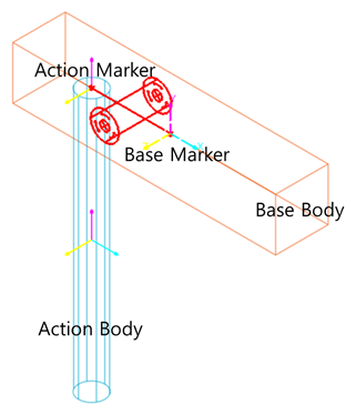
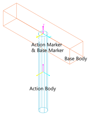
For example, consider the Figure 1 below. The vertical cylinder is the Action Body and in the left frame it is located to the left of the position that it had when the Revolute Joint was defined. The base marker is shown to the right. When the simulation begins, the cylinder will be “snapped” to the right such that the joint markers are aligned.
Figure 1 Joint closure at the start of a simulation
Degree of Freedom
|
Joint Name |
Const.No |
DOF.No |
DOF.Axis |
|
Revolute |
Tra : 3 Rot : 2 |
Tra : 0 Rot : 1 |
Z |
|
Translational |
Tra : 2 Rot : 3 |
Tra : 1 Rot : 0 |
Z |
|
Spherical |
Tra : 3 Rot : 0 |
Tra : 0 Rot : 3 |
X Y Z |
|
Cylindrical |
Tra : 2 Rot : 2 |
Tra : 1 Rot : 1 |
Z Z |
|
Universal |
Tra : 3 Rot : 1 |
Tra : 0 Rot : 2 |
X, Z |
|
Constant Velocity |
Tra : 3 Rot : 1 |
Tra : 0 Rot : 2 |
|
|
Planar |
Tra : 1 Rot : 2 |
Tra : 2 Rot : 1 |
X, Y Z |
|
Screw |
Tra : 3 Rot : 2 |
Tra : 0 Rot : 1 |
Z |
|
Fixed |
Tra : 3 Rot : 3 |
Tra : 0 Rot : 0 |
|