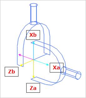
An universal joint provides the proper kinematics for joining two yoke bodies through a cross-shaped link as shown in the Figure 1. This joint has two rotational degrees of freedom, namely the rotations about the two cross axes. It is especially effective when transferring rotational motion around corners, when the user needs to simulate the non-constant velocity of a physical universal joint, or when transferring rotational motion between two connected shafts that are permitted to bend at the connection point (such as the drive shaft on an automobile). The location point of the universal joint displays the connection point of the two parts. For a universal joint, the cross bars identify the axes about which the two parts are permitted to rotate with respect to each other. The z-axis for each yoke marker is oriented along the corresponding rotational axis for the cross. The x-axis for each yoke marker is oriented along the centerline of the yoke.
Figure 1 Universal Joint icon on Working Window
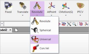
Figure 2 Universal icon of the Joint group in the Professional tab