A desired TrackLM system can be created by user-defined CAD entities which are not provided in RecurDyn. The user can use the same basic parameter and the user should input the information of the side contact with the Track Link. Because the contact is performed by the inner algorithm, only it is necessary to construct the contact surface.
The user can have following benefits by the user-defined CAD entities
•Using their own CAD geometries
•Obtaining more detail solutions
•Converting easily from the Track Link body to the Flexible Track Link body using the Convertor and Mesh tools.
The user can model the Track (LM) CAD entities with RecurDyn’s Track (LM) entities. The following combinations are possible as shown in the below table.
|
RecurDyn Track(LM) Flange Entities + User-defined Track(LM) Link Entity |
O |
|
User-defined Track(LM) Flange Entities + User-defined Track(LM) Link Entity |
O |
|
User-defined Track(LM) Flange Entities + RecurDyn Track(LM) Link Entity |
X |
If the user considers the FE result of the link as the most important result, the user can perform the modeling by the second combination and it is recommended to create the mesh for a link. Also, the user should be careful to define a side contact when performing the modeling by the user-defined CAD entities.
How to Determine the Direction of a Side Contact
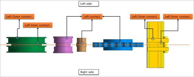
When user defines a side contact, all side contacts of Track (LM) CAD entities must be defined to the same side for the whole Track (LM) entities.
For example, if the user defines the upper part of the Track Link by the left side contact, the user has to define the same direction when creating the left side contact of other Track (LM) entities as follows.
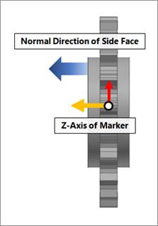
Figure 1 Side contact surface
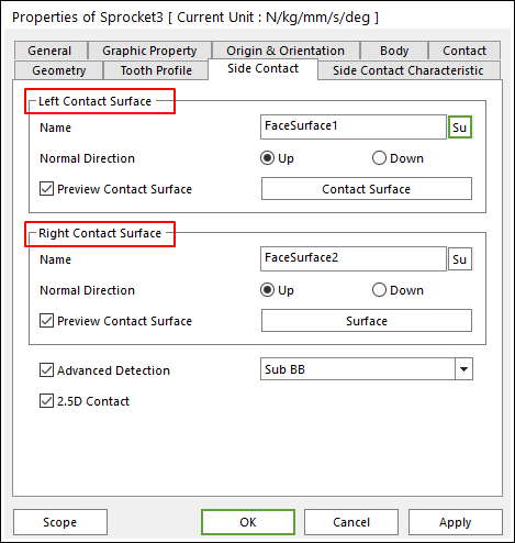
Figure 2 Defining the Side Contact in the Sprocket Property page
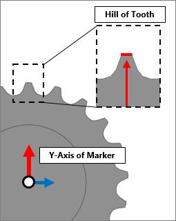
The user should set reference frame of user’s CAD geometry as the following figure. And then the geometry should be exported for in RecurDyn. Because RecurDyn creates the CAD Track Entity with referring to the reference frame of CAD geometry. And all parameters except side contact of CAD Track Entity are defined by that reference frame.
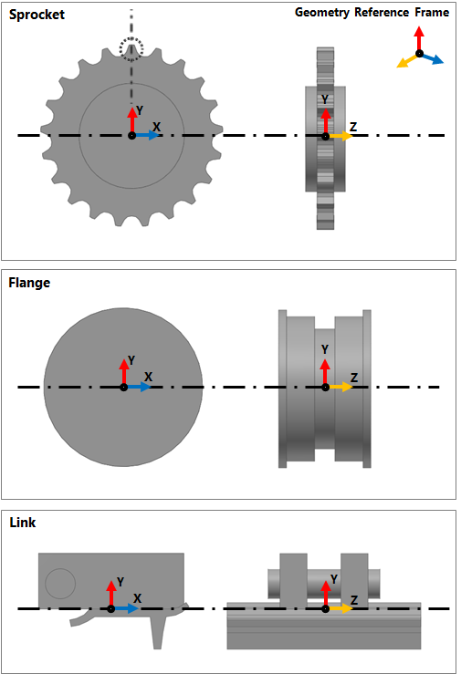
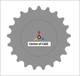
Figure 3 Geometry reference frame of CAD Track Entities
The user can adjust the geometry reference frame in RecurDyn. The following example is using Sprocket cad geometry. For the other entities, the user can adjust it as the same step.
1. Checking the Geometry Reference Frame
① Enter in Body Edit mode.
② Selects the geometry. Then the geometry reference frame is displayed on Working Window. Generally, the geometry reference frame is same to inertia marker.
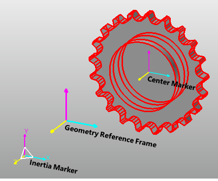
Figure 4 Checking the geometry reference frame
2. Setting the Geometry Reference Frame
① Enter in Body Edit mode.
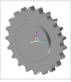
② Create a marker on the center of CAD geometry.
③ Modify the position and orientation of the created marker like the below figure.
④ Create a new marker on “0,0,0” position and set orientation like Inertia Marker.
⑤ Input the two marker on Tra/Rot tab in Basic Object Control dialog. Then the Cartesian Coordinate and Angle313(Deg) are calculated automatically, that value is different between two markers.
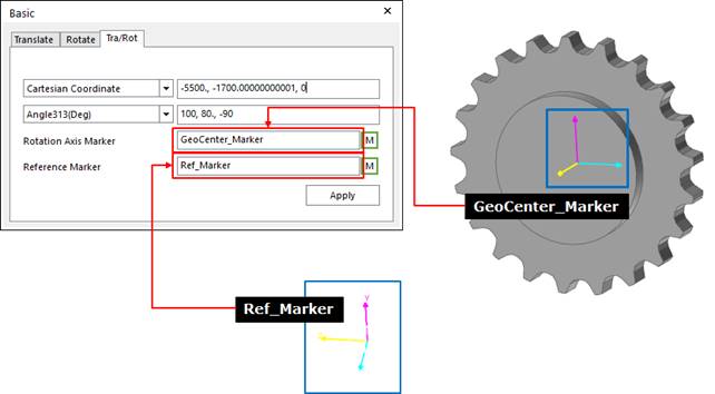
⑥ Set the Cartesian Coordinate and Angle313(Deg) value as “0,0,0”.
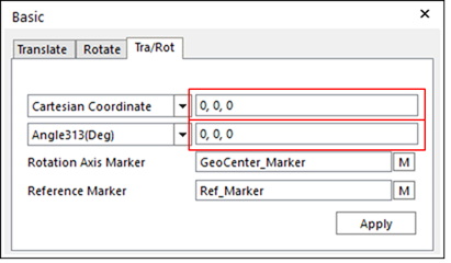
⑦ Select the CAD geometry and click Apply. Then the CAD geometry move to Inertia Marker.
⑧ Export the geometry and re-import it. Then the geometry reference frame is modified.