The basic parameters of CAD center flange are same to the basic parameters of Center Flange provided in Track_LM Toolkit. But, the user should construct a side contact between the Track Link and the CAD center flange. The following steps explains how to create a user-defined CAD center flange.
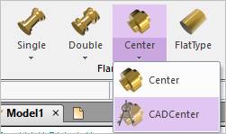
Figure 1 CAD Center icon of the Flange group in the Track(LM) tab
Step to Create a CAD Center Flange
1. Import or create a user-defined CAD center flange geometry.
2. Click the CAD Center icon of the Flange group in the Track (LM) tab
•Solid: Selects a desired solid body. (The geometry reference frame of the desired solid must be on the Inertia Marker. For more information, refer to Preparing for CAD Track Entity)
•Point: Selects a point where the CAD Center Flange is created.
3. Define a contact surface for the side contact with the Track Link after creating the CAD Center Flange.
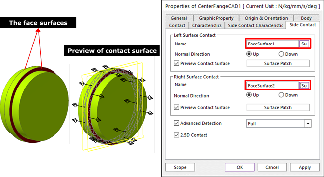
① Enter in Body Edit mode.
② Create surfaces by using Face Surface. The user can also use other generating surface tools (importing a surface geometry etc…).
③ Define the contact surfaces in Side Contact page. For more information, refer to Contact page of Contact.
④ Define contact characteristic of the Side Contact. For more information, refer to Characteristic page of Contact.