The basic parameters of CAD sprocket are same to the basic parameters of Sprocket provided in Track_LM Toolkit. But, the user should construct a side contact between the Track Link and the CAD sprocket. The following steps explain how to create a user-defined CAD Sprocket.
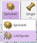
Figure 1 CAD Sprocket icon of the Sprocket group in the Track(LM) tab
Terminology
The following figure explains parameters of CAD Sprocket. The user should know the parameter’s value for setting in RecurDyn.
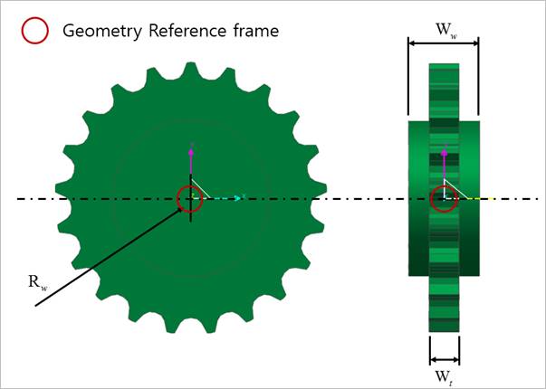
Figure 2 The user defined CAD Sprocket geometry
•Rw : Sprocket wheel radius
•Ww : Width of the outer edges of the hub
•Wt : Width of the teeth
Step to Create a CAD Sprocket
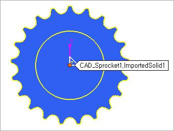
1. Import or create a user-defined CAD sprocket geometry.
2. Click the CAD Sprocket icon of the Sprocket group in the Track (LM) tab.
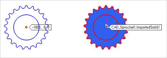
•Solid: Selects a desired solid body. (The geometry reference frame of the desired solid must be on the Inertia Marker. For more information, refer to Preparing for CAD Track Entity)
•Point: Selects a point where the CAD Sprocket is created.
•WithDialog: Inputs user-defined CAD Sprocket information (Geometry, Tooth Profile). For more information, refer to Sprocket.
•Geometry: Inputs sprocket’s geometry information.
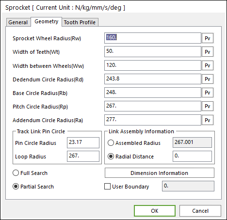
Figure 3 Sprocket property page [Geometry Data page]
•Tooth Profile: Inputs sprocket’s tooth information. Values of profile can be gotten from the solid body and these values are defined with respect to the geometry reference frame of the solid body.
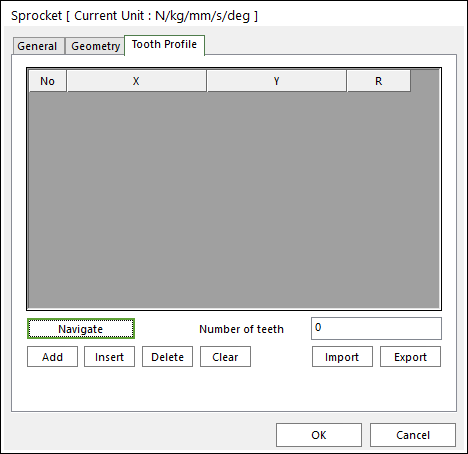
Figure 4 CAD Sprocket property page [Tooth Profile page]
o Navigation: Selects edges to define the tooth profile in a clockwise direction.
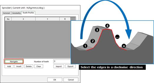
Figure 5 How to use the Navigate function
o Number of teeth: Enters the number of tooth.
3. Define a contact surface for the side contact with the Track Link after creating the CAD Sprocket.
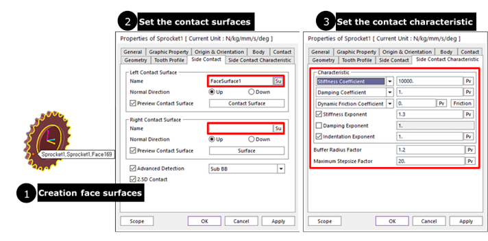
Figure 6 How to define side contact surfaces
① Enter in Body Edit mode.
② Create surfaces by using Face Surface. The user can also use other generating surface tools (importing a surface geometry etc…).
③ Define the contact surfaces in Side Contact page. For more information, refer to Contact page of Contact.
④ Define contact characteristic of the Side Contact. For more information, refer to Characteristic page of Contact.