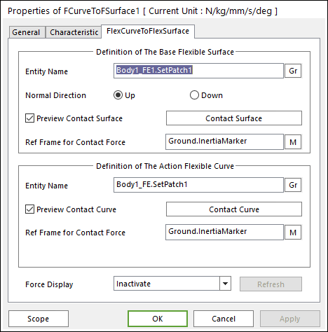
Figure 1 FCurveToFSurface property page
•Definition of the Base Flexible Surface
•Entity Name: The name of base patch set. The base patch set can be dispatched from the screen by clicking Gr.
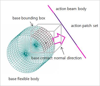
Figure 2 Preview of the normal directions, contact patches and boundary box
•Normal Direction: The normal direction of base patch set for a contact as shown in Figure 2. For more information, click here.
•Preview Contact Surface: If this option is checked, the patches making the contact surface and its boundary box are highlighted on the screen as shown in Figure 2.
•Contact Surface: Accessing Contact Surface dialog. For more information, click here.
•Ref. Frame for Contact Surface: The contact force applied on the base body is reported as a force generalized on the defined marker. If the marker is not defined, the default is Ground.Inertia Marker.
•Definition of the Action Flexible Curve
•Entity Name: The name of action patch set. The action patch set can be dispatched from the screen by clicking Gr.
•Preview Contact Surface: If this option is checked, the patches making the contact surface are highlighted on the screen as shown in Figure 2.
•Contact Curve: Accessing Contact Curve dialog box as shown in Figure 3.
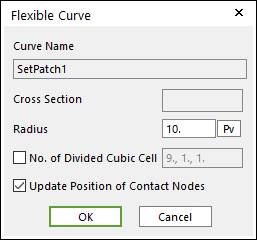
Figure 3 Flexible Curve dialog box
o Cross Section: The cross section of beam patch set. The cross section is a circle.
o Radius: The radius of circle. The radius of cylinder and sphere of the contact geometry is determined by this value.
o No. of Divided Cubic Cell: The number of cubic cells dividing a contact boundary box. This value is automatically calculated. But if need be, the value can be modified by user.
o Update Position of Contact Nodes: A flag whether the position of nodes belong to the patch set is updated during a simulation. If your system is the small deformation problem and this option is off, the solving time can be improved.
•Ref. Frame for Contact Surface: The contact force applied on the action body is reported as a force generalized on the defined marker. If the marker is not defined, the default is Ground.Inertia Marker.
•Force Display: You can graphically display the resultant force vector on the view window. For more information, click here.
•Refresh: When the action or base contact patch set is changed, you can refresh the preview of the information of the specified contact patch set as using this function.