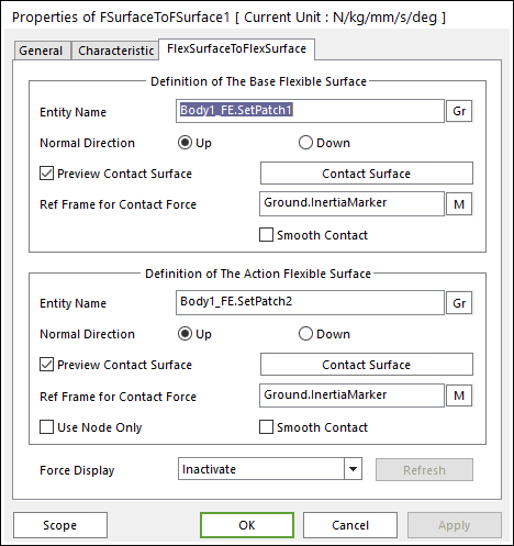
Figure 1 FSurfaceToFSurface property pge
•Definition of the Base Flexible Surface
•Entity Name: Defines the name of base patch set. The base patch set is dispatched from the screen by clicking Gr.
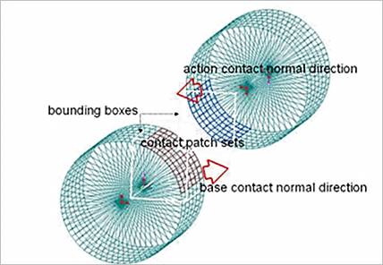
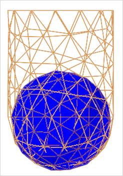
Figure 2 Preview of the normal directions, contact patches and boundary box
•Normal Direction: The normal direction of base patch set for a contact as shown in Figure 2.
o The contact is available in the specified direction.
o As selecting the “Up” or “Down”, you can change the contact direction of a base surface.
o If this page is activated, the normal direction is automatically shown on the screen.
•Preview Contact Surface: If this option is checked, the patches making the contact surface and its boundary box are highlighted on the screen.
•Contact Surface: Allows you to access the Contact Surface dialog box as shown Figure 3.
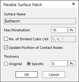
Figure 3 Flexible Surface Patch dialog box
o Max Penetration: Is the maximum penetration. If the penetration is greater than this value, then the contact force is not generated.
o No. of Divided Cubic Cell: The number of cubic cells dividing a contact boundary box. This value is automatically calculated. But if it needs, the value can be modified by the user.
o Update Position of Contact Nodes: A flag whether the position of nodes belong to the patch set is updated during a simulation. If your system is the small deformation problem and this option is unchecked, then the solving time can be improved.
o Thickness Definition: Thickness of patch is defined in the Original or Specific type. The original type uses thickness of shell property. The specific type uses User-defined thickness.
•Ref. Frame for Contact Surface: The contact force applied on the base body is reported as a force generalized on the defined marker. If the marker is not defined, the default is Ground.Inertia Marker.
•Smooth contact: Is to use the curve surface on base patch set. So, if this option is used, the contact is continuously applied on Flexible surface.
•Definition of the Action Flexible Surface
•Entity Name: Defines the name of the action patch set. The action patch set is dispatched from the screen by clicking Gr.
•Normal Direction: Is the normal direction of action patch set for a contact as shown in Figure 2. For more information, click here.
•Preview Contact Surface: If this option is checked, the patches making the contact surface and its boundary box are highlighted on the screen.
•Contact Surface: Allows you to access the dialog box of Contact Surface as shown Figure 3. For more information, click here.
•Ref. Frame for Contact Surface: The contact force applied on the action body is reported as a force generalized on the defined marker. If the marker is not defined, then the default is Ground.Inertia Marker.
•Use Node Only: Only nodes of the action surface are examined in searching for a contact point. Generally, this option can be very useful for accuracy and solving speed as will be observed in the following case.
o If the user does not use this option, the contact is applied as patch shape only.
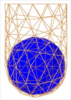
o If the user uses this option, the contact is applied as flexible body shape more correctly.
•Smooth contact: Is to use the curve surface on action patch set. So, if this option is used, the Contact is continuously applied on the Flexible Surface.
•Force Display: You can graphically display the resultant force vector on the view window. For more information, click here.
•Refresh: When the action or base contact patch set is changed, you can refresh the preview of information of specified contact patch set as using this function.