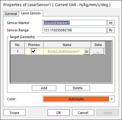
Figure 1 Laser Sensor property page
•Sensor Marker: Defines a sensor marker. The sensor marker’s position and the Z direction is used as the starting point and the direction of laser.
•Sensor Range: Defines the maximum range of laser. If the target geometry is met over the range, the result is neglected.
•Target Geometry: Defines the target of laser. When laser meets the target at first, the length from the laser to meeting position is returned as a result.
•Gr: choose a different Target Geometry.
•Data
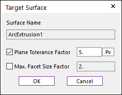
Figure 2 Target Surface dialog box
o Plane Tolerance Factor: Specifies the surface tolerance factor as a value from 0 to 10. A smaller value produces a more refined patch. For more information, click here.
o Max. Facet Size Factor: Specifies the max.facet size factor as a value from 0 to 10. This value controls the maximum size of triangular patch length. For more information, click here.
•Add: Adds some of the target geometry.
•Delete: Deletes some of the target geometry.
•Color: Defines the color of sensor icon.