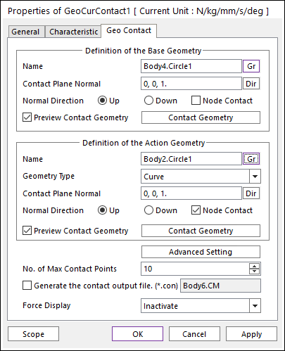
Figure 1-1 Properties of GeoCurContact dialog box [Curve type]
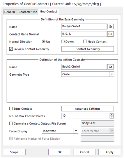
Figure 1-2 Properties of GeoCurContact dialog box [Circle Type]
•Definition of the Base Geometry
•Name: Defines the name of base curve geometry. The base curve geometry can be modified from the Working Window by clicking Gr. The Line set of a flexible body (Fflex or Rflex) can be defined to the base curve geometry.
•Contact Plane Normal: Defines the contact plane for base curve geometry in order to define the 2D contact. By using this contact plane normal direction, the user can define any kind of 2D contact problem. In most cases, the base contact plane normal should be same with the action contact plane normal.
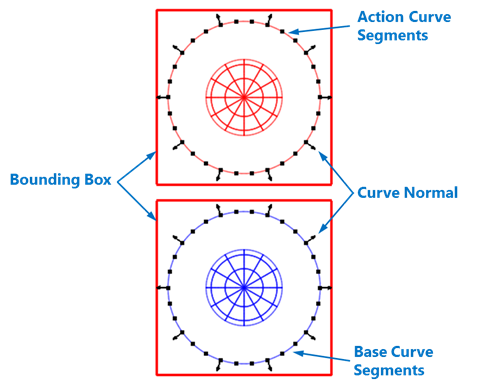
Figure 2 Preview of the normal directions, bounding boxes, contact segments and nodes.
•Normal Direction: Defines the normal direction of a base geometry for a contact as shown in the above figure.
o The contact is available in the specified direction.
o As selecting “Up” or “Down”, the user can change the contact direction of a base geometry.
o If this page is activated, the normal direction is automatically shown on the Working Window.
•Node Contact: If this option is checked, the contact force by the base node is calculated.
•Preview Contact Geometry: If this option is checked, the segments for the base curve are shown on the Working Window as shown in the above figure.
•Contact Geometry: Accesses the Curve Segment dialog box for the base geometry as shown in the below figure.
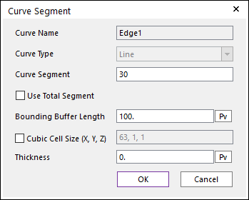
Figure 3 Curve Segment dialog box for a rigid body
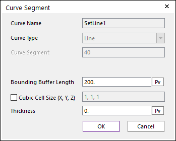
Figure 4 Curve Segment dialog box for a flexible body
o Curve Name: This shows the name of the selected base contact geometry.
o Curve Type: This shows the faceting method for the curve geometry. In the current version, only “Line” type is supported.
o Use Total Segment: If this option is selected, the user can make approximately equally spaced contact segments on the curve by using the “Curve Segment” information although there are multiple edges in a curve geometry. This option is available for a rigid body.
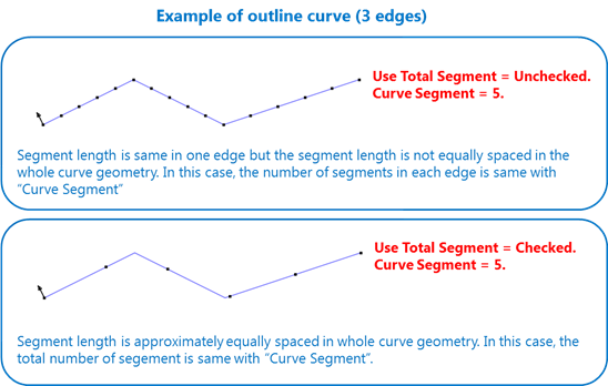
Figure 5 The example of “Use Total Segment” option in the case of “Curve Segment = 5”.
o Curve Segment: If the “Use Total Segment” option is not checked, “Curve Segment” means the number of segments in an edge or the number of segments between the user specified control points. If the “Use Total Segment” option is checked, Curve Segment means the number of segments in the whole connected edge. If the user increases this number, the number of points is increased and the approximated contact curve is close to the real curve. If the curve is a Line Set of a flexible body, this value just shows the number of lines including the Line Set. The maximum number of total curve segments is 500,000.
o Bounding Buffer Length: This value is used when the contact pre-search is performed with base and action bounding box. The bounding buffer length defines the offset length of bounding box compared to the real bounding box as shown in the below figure. This value is automatically calculated, but can be modified by the user.
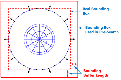
Figure 6 Definition of Bounding Buffer Length
o Cubic Cell Size (X, Y, Z): Shows the number of cubic cells dividing a contact bounding box in each direction. This value is automatically calculated, but can be modified by the user.
o Thickness: Define thickness of curve. This value is reflected on the contact penetration calculation.
•Definition of the Action Geometry
•Name: Defines the name of action geometry. The action geometry can be modified from the Working Window by clicking Gr. The Line set of a flexible body (Fflex or Rflex) can be defined to the action curve geometry. Additionally, if the user wants to use Circle type as Geometry type, the circle or sphere geometry should be defined.
•Geometry Type: Defines geometry type of action body. In the case of Curve type, the line set or edge of the action geometry are used to the contact. In the case of Circle type, the circle or sphere geometry is used to the contact.
•Contact Plane Normal: Defines the contact plane for the action curve geometry in order to define the 2D contact. By using this contact plane normal direction, the user can define any kind of 2D contact problem. In most cases, the action contact plane normal should be same with the base contact plane normal. There is no contact plane normal in the case of circle geometry type.
•Normal Direction: Defines the normal direction of an action geometry for a contact. For more information, click here.
•Node Contact: If this option is checked, the contact force by the action node is calculated.
•Preview Contact Geometry: If this option is checked, the segments for the action curve are shown on the Working Window.
•Contact Geometry: Accesses the Curve Segment dialog box for the action geometry. In the case of Circle type as Geometry type, this function doesn’t appears. For more information, click here.
•Edge Contact
•In the case of Circle type, if this option is checked, the contact force by the circle and base edges is calculated. In order to perform the reasonable contact analysis in some models such as the below figure, “Edge Contact” option must be used.
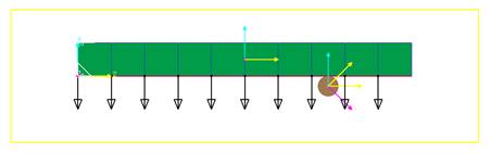
Figure 7 Example of Edge Contact Option [Circle type]
•Advanced Settings: Accesses the Advanced Settings dialog box as shown in the below figure.
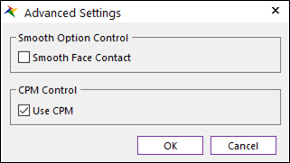
Figure 8-1 Advanced Settings dialog box [Curve type]
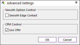
Figure 8-2 Advanced Settings dialog box [Circle type]
o Smooth Node Contact: If this option is checked, the smooth contact algorithm is applied in node-to-segment collision pattern and the corresponding segment is smoothed by using the cubic Hermite spline equation. The cubic Hermite spline equation is generated by using the node position and segment normal direction at node.
o Smooth Edge Contact: In the case of Circle type as Geometry type, this option is activated. If this option is checked, the smooth contact algorithm is applied in circle-to-curve collision pattern. This algorithm finds optimum contact point between circle and 3-order cubic spline curve which is expressed as nodal position and tangential direction of segment. spline equation. If user selects this option, base node contact are not recommended in most cases because the smooth option is applied in the edge contact.
o Use CPM: CPM is the abbreviation of Consistent Penetration Method. If this option is checked, the contact force at each contact point is divided by the total number of contact points. As a result, although user uses different facet or element size for the geometry, total contact force magnitude will be remained in similar level. This means that the user does not need to change the contact stiffness or contact damping parameters when the user uses different mesh or different faceting values for the same geometry. On the other hand, if this option is unchecked, the contact force is applied for the all contact points with given contact parameters.
•No. of Max Contact Point: Defines the number of max contact point for output. User can define this value from 1 to 5000. This value only affect Force Display and RPLT data about contact points.
•Generate the contact output file(*.con): When user checks Generate the contact output file, RecurDyn creates the contact output file based on the contact output reference. The user can calculate the local contact information based on the contact output reference by using *.con output file. Then RecurDyn/Solver reports all contact-related information in order of contact force magnitude to the text file. The format is as follows:
|
Variables |
Descriptions | |
|
1 |
Time |
Simulation Time |
|
2 |
NCP |
Total number of calculated contact points |
|
3 |
NO |
Current contact point number |
|
4 |
X_RefPos |
Position X of Output Reference Marker from Global |
|
5 |
Y_RefPos |
Position Y of Output Reference Marker from Global |
|
6 |
Z_RefPos |
Position Z of Output Reference Marker from Global |
|
7 |
Z_EulerA |
Z Euler Angle of Output Reference Marker from Global |
|
8 |
X_EulerA |
X Euler Angle of Output Reference Marker from Global |
|
9 |
Z_EulerA |
Z Euler Angle of Output Reference Marker from Global |
|
10 |
X_ConPos |
Position X of Calculated Contact Reference Frame from Global |
|
11 |
Y_ConPos |
Position Y of Calculated Contact Reference Frame from Global |
|
12 |
Z_ConPos |
Position Z of Calculated Contact Reference Frame from Global |
|
13 |
X_NorDir |
Normal Direction X of Calculated Contact Reference Frame from Global |
|
14 |
Y_NorDir |
Normal Direction Y of Calculated Contact Reference Frame from Global |
|
15 |
Z_NorDir |
Normal Direction Z of Calculated Contact Reference Frame from Global |
|
16 |
X_TanDir |
Tangent(Friction) Direction X of Calculated Contact Reference Frame from Global |
|
17 |
Y_TanDir |
Tangent(Friction) Direction Y of Calculated Contact Reference Frame from Global |
|
18 |
Z_TanDir |
Tangent(Friction) Direction Z of Calculated Contact Reference Frame from Global |
|
19 |
Pen |
Penetration Depth |
|
20 |
PenVel |
Penetration Depth Velocity or Relative Velocity in Normal Direction |
|
21 |
TanVel |
Relative Velocity in Tangent Direction |
|
22 |
FricCoeff |
Friction Coefficient |
|
23 |
NorForce |
Normal Force Magnitude |
|
24 |
FricForce |
Friction Force Magnitude |
•Force Display: Graphically displays the all contact force vectors (the sum of the normal and tangential contact force) at the each contact point up to the “No. of Max Contact Point. For more information, click here.