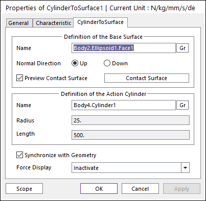
Figure 1 Properties of CylinderToSurface dialog box
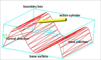
Figure 2 Preview of the normal directions, contact patches and boundary box
•Definition of The Base Surface
•Entity Name: Defines the name of base surface. The base surface can be dispatched from the Working Window by clicking Gr.
•Normal Direction: Defines the normal direction of a base surface for a contact as shown in Figure 2. For more information, click here.
•Preview Contact Surface: If this button is checked, the patches making the contact surface and its boundary box are shown on the Working Window as shown.
•Contact Surface: Accesses the Contact Surface dialog box. For more information, click here.
•Definition of The Action Cylinder
•Entity Name: Defines the name of action cylinder. The action cylinder can be dispatched from the Working Window by clicking Gr.
•Radius: Shows the radius of action cylinder.
•Length: Shows the length of action cylinder.
•Synchronize with Geometry
o If this option is checked, Radius and Length in contact properties are automatically defined with that of the specified graphics. (The default is checked)
o If this option is not checked, the user can modify the contact properties.
•Force Display: Graphically displays the resultant force vector on the view window. For more information, click here.