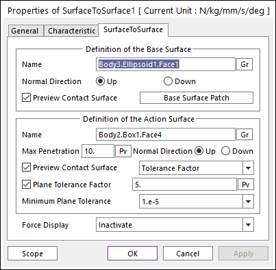
Figure 1 Properties of SurfaceToSurface dialog box
•Definition of The Base Surface
•Entity Name: Defines the name of base surface. The base surface can be dispatched from the Working Window by clicking Gr.

Figure 2 Preview of the normal directions, contact patches and nodes
•Normal Direction: Defines the normal direction of base surface for a contact as shown in Figure 2. For more information, click here.
•Preview Contact Surface: If this option is checked, the patches making the contact surface are shown on the Working Window as shown.
•Base Surface Patch: Accesses the Base Surface Patch dialog box. For more information, click here.
•Definition of The Action Surface
•Entity Name: Defines the name of action surface. The action surface can be dispatched from the Working Window by clicking Gr.
•Max Penetration: Defines the maximum penetration. If the penetration is greater than this value, the contact force is not generated.
•Normal Direction: Defines the normal direction of an action surface for a contact as shown in Figure 2. For more information, click here.
•Preview Contact Surface: If this option is checked, the nodes making the contact surface are shown on the Working Window as shown.
•Plane Tolerance Factor: Specifies the surface tolerance factor as a value from 0 to 10. For more information, click here.

Figure 3 UV precision of an action surface
•UV Precision: If a surface is created by using the outline or spline surface in the Body Edit Mode, the number of nodes for contact surface can be controlled with the UV Precision Factor. As shown in Figure 3, the U and V factor in the upper surface are defined as 1 and 1. In the lower surface, the U and V factor are defined as 5 and 3.
•Force Display: Graphically displays the resultant force vector on the view window. For more information, click here.