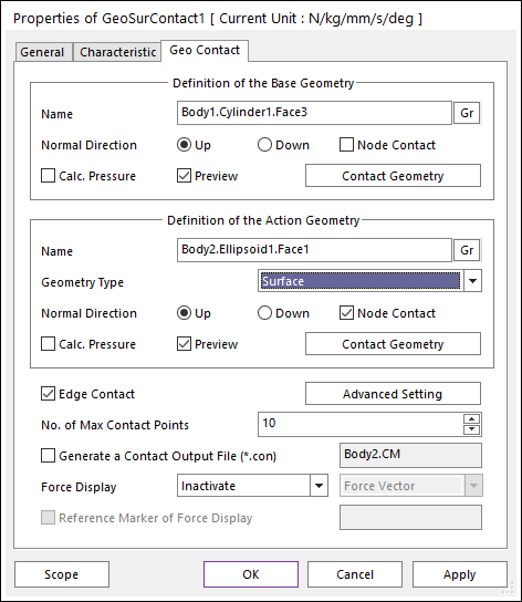
Figure 1-1 Properties of Geo Surface Contact dialog box [Surface type]
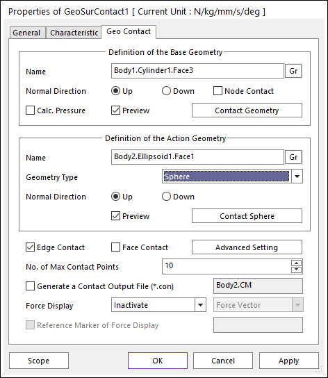
Figure 1-2 Properties of Geo Surface Contact dialog box [Sphere type]
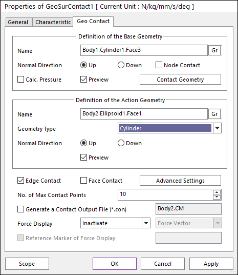
Figure 1-3 Properties of Geo Surface Contact dialog box [Cylinder type]
•Definition of the Base Geometry
•Name: Defines the name of base geometry. The base geometry can be modified from the Working Window by clicking Gr.
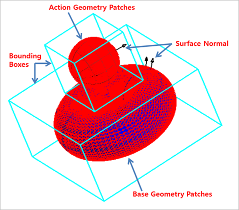
Figure 2 Preview of the normal directions, contact patches and nodes.
•Normal Direction: Defines the normal direction of a base geometry for a contact as shown in the above figure.
o The contact is available in the specified direction.
o As selecting “Up” or “Down”, the user can change the contact direction of a base geometry.
o If this page is activated, the normal direction is automatically shown on the Working Window.
•Calculate Pressure: Calculates contact pressure for surface type geometry. Contour file is created when this option is activated. Note that Calculate Pressure option is supported only for rigid body surfaces.
o The calculated pressure result is calculated on each node. Pressure is calculated by an area and a force projected to the node. The force value for pressure is calculated by the forces that occur around the node. And the area value for pressure is calculated by the patches and size of the patches around the node.
•Preview: If this option is checked, the patches making the contact surface are shown on the Working Window as shown in the above figure.
•Node Contact: If this option is checked, the contact force by the base node is calculated.
•Contact Geometry: Accesses the Surface Patch dialog box as shown in the below figure.
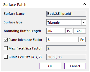
Figure 3 Surface Patch dialog box
o Surface Name: This shows the name of the selected base contact geometry.
o Surface Type: Select the “Triangle” for the triangle faceting or select the “Quad” for the quad-dominant faceting. In the “Triangle” type, the contact surface is approximated to multiple triangular patches. On the other hand, in the “Quad” type, the contact surface is approximated to multiple triangular and quadrilateral patches.
o Bounding Buffer Length: This value is used when the contact pre-search is performed with base and action bounding box. The bounding buffer length defines the offset length of bounding box compared to the real bounding box as shown in the below figure. This value is automatically calculated but can be modified by the user. Additionally, if you click Cal., this value is updated with the recommended default value.
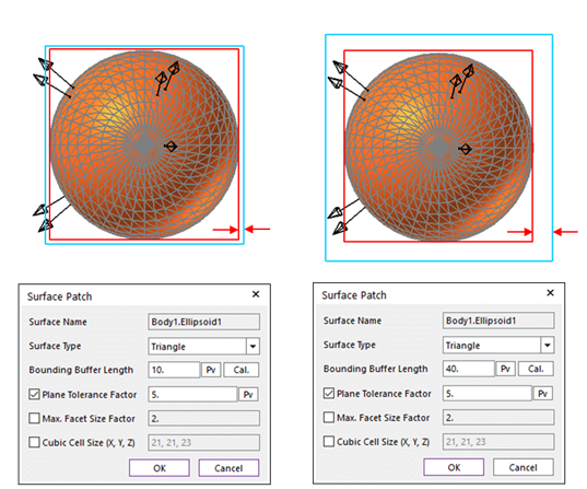
Figure 4 Definition of Bounding Buffer Length
o Plane Tolerance Factor: Specifies the surface tolerance factor as a value from 0.01 to 10. A smaller value produces more refined patches. For more information, click here.
o Max. Facet Size Factor: Specifies the max. facet size factor as a value from 0.01 to 10. This value controls the maximum size of triangular or quadrilateral patch length. Even though box geometry, if this value is defined (checked), box geometry can be used with lots of triangular or quadrilateral patches as shown in the below figure.
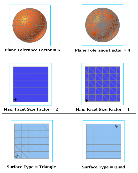
Figure 5 Example of Plane Tolerance Factor, Max. Facet Size Factor and Quad Surface Type
o Cubic Cell Size: Shows the number of cubic cells dividing a contact bounding box in each direction. This value is automatically calculated but can be modified by the user.
•Definition of the Action Geometry
•Name: Defines the name of action geometry. The action geometry can be modified from the Working Window by clicking Gr. If the user wants to use Sphere type as Geometry type, the sphere geometry should be defined.
•Geometry Type: Defines geometry type of action body. In the case of Surface type, the patches of the action geometry are used to the contact. In the case of Sphere type, the sphere geometry is used to the contact.
•Normal Direction: Defines the normal direction of an action geometry for a contact. For more information, click here.
•Calculate Pressure: Calculates contact pressure for surface type geometry. This option is activated only when the geometry type is surface. Contour file is created when this option is activated. Note that Calculate Pressure option is supported only for rigid body surfaces.
o The calculated pressure result is calculated on each node. Pressure is calculated by an area and a force projected to the node. The force value for pressure is calculated by the forces that occur around the node. And the area value for pressure is calculated by the patches and size of the patches around the node.
•Preview: If this option is checked, the patches making the contact surface are shown on the Working Window.
•Node Contact: In the case of Surface type as Geometry type, this option is activated. If this option is checked, the contact force by the action node is calculated.
•Contact Geometry: Accesses the Surface Patch dialog box. In the case of Surface type as Geometry type, this function is activated. For more information, click here.
•Edge Contact
•In the case of Surface type as Geometry type, if this option is checked, the contact force by the base and action edges is calculated. In order to perform the reasonable contact analysis in some models such as the below figure, “Edge Contact” option must be used.
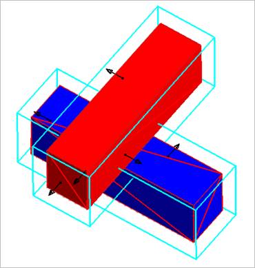
Figure 6-1 Example of Edge Contact Option [Surface type]
•In the case of Sphere type as Geometry type, if this option is checked, the contact force by the base edge and the action sphere is calculated. In order to perform the reasonable contact analysis in some cases such as the below figure situation in which sphere is in contact with a corner edge, “Edge Contact” option can give more accurate results than a node or a face contact option. But, in general cases, this edge option is not recommended than a node or a face option in the Geo Sphere contact.
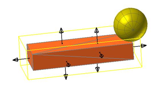
Figure 6-2 Example of Edge Contact Option [Sphere type]
•In the case of Cylinder type as Geometry type, if this option is checked, the contact force by the base edge and the action cylinder is calculated. In order to perform the reasonable contact analysis in some cases such as the below figure situation in which cylinder is in contact with edges, “Edge Contact” option can give more accurate results than a node or a face contact option.
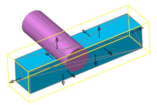
Figure 6-3 Example of Edge Contact Option [Cylinder type]
•Face Contact
•In the case of Sphere type as Geometry type, this option is activated. If this option is checked, the contact force by the base patches and the action sphere is calculated. In order to perform the reasonable contact analysis in some cases such as the below figure in which sphere is in contact with a patch, “Face Contact” option must be used.
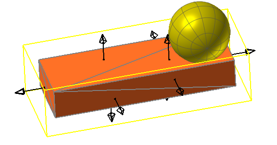
Figure 7-1 Example of Face Contact Option [Sphere type]
•In the case of Cylinder type as Geometry type, this option is activated. If this option is checked, the contact force by the base patches and the edge of action cylinder is calculated. In order to perform the reasonable contact analysis in some cases such as the below figure in which sphere is in contact with a patch, “Face Contact” option must be used. But, in general cases, this face option is not recommended than a node or an edge option in the Geo Cylinder contact.
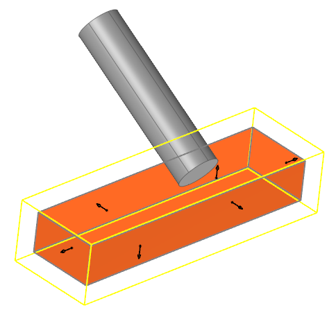
Figure 7-2 Example of Face Contact Option [Cylinder type]
•Advanced Settings: Accesses the Advanced Settings dialog box as shown in the below figure.
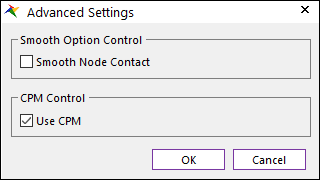
Figure 8-1 Advanced Settings dialog box [Surface type]
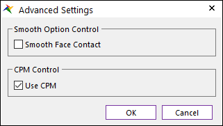
Figure 8-2 Advanced Settings dialog box [Sphere type]
•Smooth Face Contact: In the case of Sphere type as Geometry type, this option is activated. If this option is checked, the smooth contact algorithm is applied in sphere-to-face collision pattern and the corresponding face is smoothed by using the bi-cubic Hermite surface equation. The bi-cubic Hermite surface equation is generated by using the node position and surface normal direction at node. If user selects this option, the edge and base node contact are not recommended in most cases because the smooth option is applied in the face contact.
•Use CPM: CPM is the abbreviation of Consistent Penetration Method. If this option is checked, the contact force at each contact point is divided by the total number of contact points. As a result, although user uses different facet or element size for the geometry, total contact force magnitude will be remained in similar level. This means that the user does not need to change the contact stiffness or contact damping parameters when the user uses different mesh or different faceting values for the same geometry. On the other hand, if this option is unchecked, the contact force is applied for the all contact points with given contact parameters.
•No. of Max Contact Point: Defines the number of max contact point for output. User can define this value from 1 to 5000. This value only affects Force Display and RPLT data about contact points.
•Generate the contact output file(*.con): When this option is checked, RecurDyn creates the contact output file based on the contact output reference. The user can calculate the local contact information based on the contact output reference by using *.con output file. Then RecurDyn/Solver reports all contact-related information in order of contact force magnitude to the text file. The format is as follows:
|
Variables |
Descriptions | |
|
1 |
Time |
Simulation Time |
|
2 |
NCP |
Total number of calculated contact points |
|
3 |
NO |
Current contact point number |
|
4 |
X_RefPos |
Position X of Output Reference Marker from Global |
|
5 |
Y_RefPos |
Position Y of Output Reference Marker from Global |
|
6 |
Z_RefPos |
Position Z of Output Reference Marker from Global |
|
7 |
Z_EulerA |
Z Euler Angle of Output Reference Marker from Global |
|
8 |
X_EulerA |
X Euler Angle of Output Reference Marker from Global |
|
9 |
Z_EulerA |
Z Euler Angle of Output Reference Marker from Global |
|
10 |
X_ConPos |
Position X of Calculated Contact Reference Frame from Global |
|
11 |
Y_ConPos |
Position Y of Calculated Contact Reference Frame from Global |
|
12 |
Z_ConPos |
Position Z of Calculated Contact Reference Frame from Global |
|
13 |
X_NorDir |
Normal Direction X of Calculated Contact Reference Frame from Global |
|
14 |
Y_NorDir |
Normal Direction Y of Calculated Contact Reference Frame from Global |
|
15 |
Z_NorDir |
Normal Direction Z of Calculated Contact Reference Frame from Global |
|
16 |
X_TanDir |
Tangent(Friction) Direction X of Calculated Contact Reference Frame from Global |
|
17 |
Y_TanDir |
Tangent(Friction) Direction Y of Calculated Contact Reference Frame from Global |
|
18 |
Z_TanDir |
Tangent(Friction) Direction Z of Calculated Contact Reference Frame from Global |
|
19 |
Pen |
Penetration Depth |
|
20 |
PenVel |
Penetration Depth Velocity or Relative Velocity in Normal Direction |
|
21 |
TanVel |
Relative Velocity in Tangent Direction |
|
22 |
FricCoeff |
Friction Coefficient |
|
23 |
NorForce |
Normal Force Magnitude |
|
24 |
FricForce |
Friction Force Magnitude |
•Force Display: Graphically displays the all contact force vectors (the sum of the normal and tangential contact force) at each contact point up to the “No. of Max Contact Point” as shown in the below figure. For more information, click here.
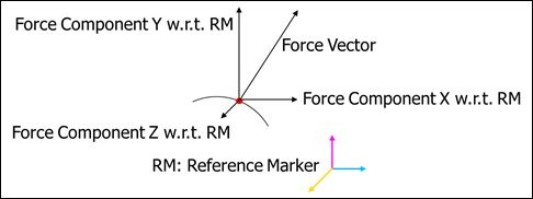
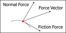
Figure 9 Option of Contact Force Display (Force Vector, Force Component X, Y, Z, Normal Force and Friction Force)
o Force Vector (default), Force Component X, Y, Z, Friction Force and Normal Force can be displayed using toggle option.
o The reference marker can select when display the Force Component X, Y, Z.
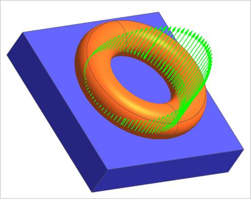
Figure 10 Example of Contact Force Display
Note
In Geo contact, the accumulated contact force result (FM,FX,FY,FZ,TM,TX,TY,TZ ) is only evaluated for the “action body”. the accumulated contact force result (FM,FX,FY,FZ,TM,TX,TY,TZ) is evaluated w.r.t. the “Ground.InertiaMarker” when the "Generate the contact output file.(*.con)" is not checked. If user checks the "Generate the contact output file.(*.con)", the user can specify the output reference frame for the accumulated contact force (FM,FX,FY,FZ,TM,TX,TY,TZ) for the action body. In the case of contact point results, they are sorted in order of contact force magnitude.