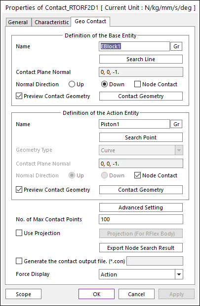
Figure 1 Rigid To RFlex Contact property page [Cylinder To Piston page]
•Definition of Base Entity: The base body for this contact should be an engine block.
•Entity Name: Enters the name of Cylinder.
•Search Line: Enables to find the contact line in the cylinder body.
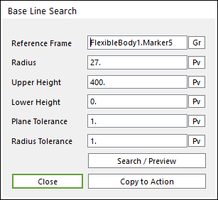
Figure 2 Base Line Search dialog box
o Reference Frame: Select a reference frame to find search line.
o Radius: Defines the radius of the inner circle.
o Upper Height: Defines the distance from reference frame to Upper Height.
o Lower Height: Defines the distance from reference frame to Lower Height.
o Plane Tolerance: Defines the plane tolerance.
o Radius Tolerance: Defines the radius tolerance (Degree).
o Copy to Action: Copy the property of this dialog to one of Search Point.
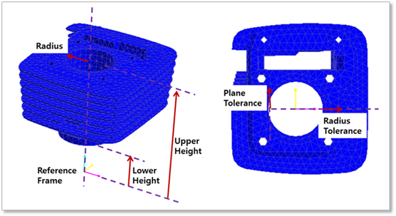
Figure 3 Definition of parameters
•Contact Plane Normal: RecurDyn/GUI set automatically.
•Normal Direction: Indicates the direction of contact and it is changed by the option as 'Up' or 'Down'.
•Node Contact: Unchecked. (Base node to Action line contact case is not supported in Rigid To RFlex contact.)
•Preview Contact Line: Shows the contact line found from Search Line.
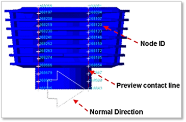
Figure 4 Showing some parameters in Working Window
•Definition of Action Entity: The action body for this contact should be a piston.
•Entity Name: Enters the name of Piston.
•Search Point: Enables to find the contact points in the piston body. The parameters in this dialog is same to Search Line.
•Preview Contact Line: Shows the contact points found from Search Point.
•Geometry Type: Curved.
•Contact Plane Normal: RecurDyn/GUI set automatically.
•Normal Direction: Not available.
•Node Contact: Checked. (Action node to Base line contact case is supported in Rigid To RFlex contact.)
•Advanced Settings: Accesses the Advanced Setting dialog box as shown in the below figure.
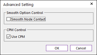
Figure 5 Advanced Setting dialog box
•Smooth Node Contact: In the case of Surface type as Geometry type, this option is activated. If this option is checked, the smooth contact algorithm is applied in node-to-face collision pattern and the corresponding face is smoothed by using the bi-cubic Hermite surface equation. The bi-cubic Hermite surface equation is generated by using the node position and surface normal direction at node. If user selects this option, the edge contact is not recommended in most cases because the smooth option is applied in the action and base node contacts.
•Use CPM: CPM is the abbreviation of Consistent Penetration Method. If this option is checked, the contact force at each contact point is divided by the total number of contact points. As a result, although user uses different facet or element size for the geometry, total contact force magnitude is remained in similar level. This means that the user does not need to change the contact stiffness or contact damping parameters when the user uses different mesh or different faceting values for the same geometry. On the other hand, if this option is unchecked, the contact force is applied for the all contact points with given contact parameters.
•No. of Max Contact Point: Defines the number of max contact point for output. User can define this value from 1 to 5000. This value only affects Force Display and RPLT data about contact points.
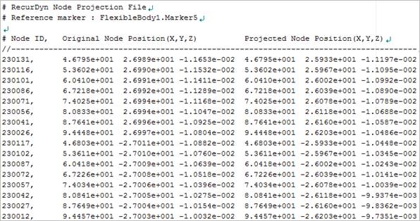
•Use Projection: Applies the node projection to the surface.
•Projection (For RFlex Body): Makes to generate the surface from the imported point data for the node projection. The data is used if Use Projection option is checked. For more information, click here.
•Export Node Search Result: Exports the original and projected position of searched nodes as a text file.
•Generate the contact output file(*.con): When user checks Generate the contact output file option, RecurDyn creates the contact output file based on the contact output reference. The user can calculate the local contact information based on the contact output reference by using *.con output file. Then RecurDyn/Solver reports all contact-related information in order of contact force magnitude to the text file. The format is as follows:
|
Variables |
Descriptions | |
|
1 |
Time |
Simulation Time |
|
2 |
NCP |
Total number of calculated contact points |
|
3 |
NO |
Current contact point number |
|
4 |
X_RefPos |
Position X of Output Reference Marker from Global |
|
5 |
Y_RefPos |
Position Y of Output Reference Marker from Global |
|
6 |
Z_RefPos |
Position Z of Output Reference Marker from Global |
|
7 |
Z_EulerA |
Z Euler Angle of Output Reference Marker from Global |
|
8 |
X_EulerA |
X Euler Angle of Output Reference Marker from Global |
|
9 |
Z_EulerA |
Z Euler Angle of Output Reference Marker from Global |
|
10 |
X_ConPos |
Position X of Calculated Contact Reference Frame from Global |
|
11 |
Y_ConPos |
Position Y of Calculated Contact Reference Frame from Global |
|
12 |
Z_ConPos |
Position Z of Calculated Contact Reference Frame from Global |
|
13 |
X_NorDir |
Normal Direction X of Calculated Contact Reference Frame from Global |
|
14 |
Y_NorDir |
Normal Direction Y of Calculated Contact Reference Frame from Global |
|
15 |
Z_NorDir |
Normal Direction Z of Calculated Contact Reference Frame from Global |
|
16 |
X_TanDir |
Tangent(Friction) Direction X of Calculated Contact Reference Frame from Global |
|
17 |
Y_TanDir |
Tangent(Friction) Direction Y of Calculated Contact Reference Frame from Global |
|
18 |
Z_TanDir |
Tangent(Friction) Direction Z of Calculated Contact Reference Frame from Global |
|
19 |
Pen |
Penetration Depth |
|
20 |
PenVel |
Penetration Depth Velocity or Relative Velocity in Normal Direction |
|
21 |
TanVel |
Relative Velocity in Tangent Direction |
|
22 |
FricCoeff |
Friction Coefficient |
|
23 |
NorForce |
Normal Force Magnitude |
|
24 |
FricForce |
Friction Force Magnitude |
•Force Display: Graphically displays the all contact force vectors (the sum of the normal and tangential contact force) at each contact point up to the “No. of Max Contact Point” as shown in the below figure. For more information, click here.