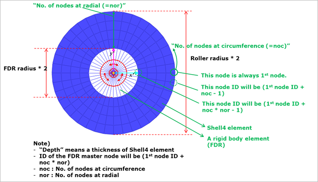
The flexible roller is a hollow circle as shown in Figure 1. The FDR and shell4 elements are used. The master node of FDR element is located at the rotational center and connected the revolute joint through a dummy body and a bushing force. The Slave nodes of FDR element are the nodes of inner circle. FDR Radius is defined as the inner circle’s radius. Roller Radius is defined the flexible roller’s radius. The shell4 elements are placed between the roller radius and the FDR radius. The shell4 elements are the same FFlex/Shell4 element (3D and Plane stress shell type element). All nodes of shell4 have 6 DOFs. In order to describe the 2D motion, TZ, RX, RY DOFs of all nodes except the FDR master node are automatically defined by Boundary Condition.
•Element: Shell4 + FDR elements
•Number of nodes: (No. of nodes at circumference) * (No. of nodes at radial) + 1
•Number of shell4 elements: (No. of nodes at circumference - 1) * (No. of nodes at radial – 1)
•Shell4 element formulation: RecurDyn FFlex/Shell4 (3D and plane stress type shell element, all node has 6 DOFs.)
•Shell4 Material property: Linear elastic/Isotropic
•Boundary condition of nodes: TZ, RX, RY (Except FDR master node)
•Contact nodes and contact edges: External nodes and edges.
Figure 1 Flexible information of Flexible roller
Figure 2 indicates where the flexible information is located in Properties dialog of the flexible roller.
The “No. of Nodes at Circumference” and “No. of Nodes at Radial” information must be set only at the creation time. After creating them, their values cannot be changed.
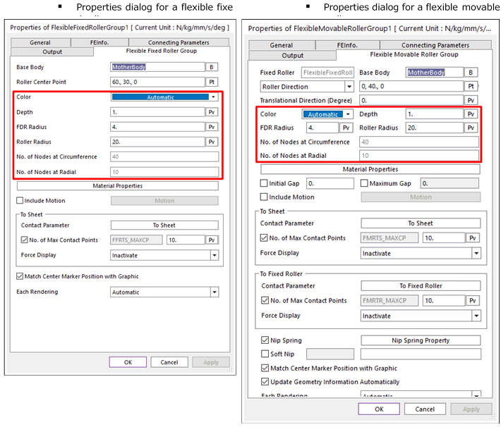
Figure 2 Properties dialog for the flexible roller
Figure 3 shows the information of material properties for flexible roller. In the material properties dialog, the user can set the material information of Shell4 and FDR elements.
“Density”, “Young’s modulus”, “Damping ratio” and “Poison’s ratio” are material properties for the Shell4 element. If the user wants to check detail information of these data, click here.
“Drilling stiffness factor” is an element property for Shell4. If the user wants to check detail information, refer to the property of SHELL element.
“FDR Young’s modulus” and “FDR damping ratio” are element properties for FDR. If the user wants to check detail information, refer to the property of FDR element.
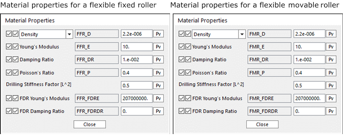
Figure 3 Material Properties for the flexible roller
Flexible Roller and Sheet Interactions
There are three contact cases between a sheet and a flexible roller.
•Contact case between the linear part of sheet and the node of flexible roller
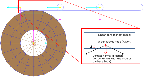
Figure 4 Contact case between the linear part and the node of flexible roller
•Contact case between the circular part of sheet and the node of flexible roller
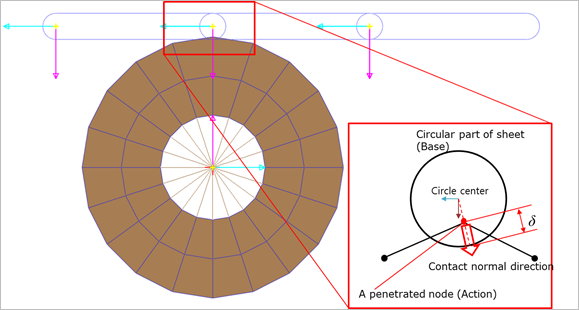
Figure 5 Contact case between the circular part of sheet and the node of flexible roller
•Contact case between the circular part of sheet and the edge of flexible roller
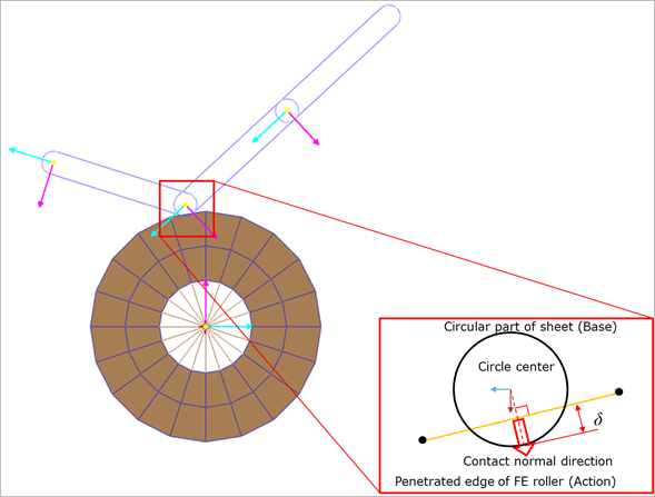
Figure 6 Contact case between the circular part of sheet and the edge of flexible roller
Flexible Roller and Roller Interactions
There are two contact cases between the rigid roller and the flexible roller.
•Contact case between the circle of roller and the node of flexible roller
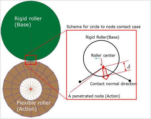
Figure 7 Contact case between the circle of roller and the node of flexible roller
•Contact case between the circle of roller and the edge of flexible roller
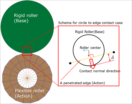
Figure 8 Contact case between the circle of roller and the edge of flexible roller
Flexible Roller and Flexible Roller Interactions
There is a contact case between a flexible roller pair.
•Contact case between the edge of flexible roller and the node of flexible roller
In this contact case, the base body has edges. And the action body has nodes. Therefore, the contact search algorithm is one, the actual search performs two times. In the 1st search, the flexible fixed roller is defined as a base body (Edge), the flexible movable roller is defined as an action body (Node). And then, in the 2nd search the base and action condition will be switched.
The contact normal direction is always perpendicular with the edge surface.
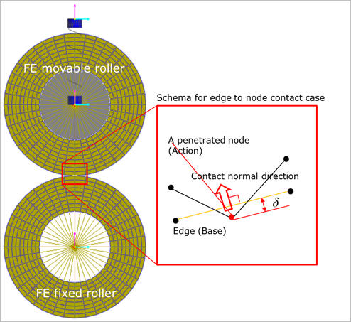
Figure 9 Contact case between the edge of flexible roller and the node of flexible roller