During assembly, a below dialog box is shown.
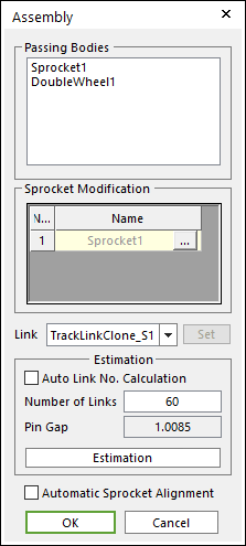
Figure 1 Assembly dialog box
•Passing Bodies: Shows the list of assembled bodies.
•Sprocket Modification: Modifies the assembly information about Sprocket. For more information, click here.
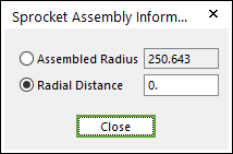
Figure 2 Sprocket Assembly Information dialog box
•Link: Selects a clone link. If the user clicks Set, the user can customize the generated link set.
•Set: The user can use link sets wanted among the defined link sets. To use this function, the user must define link sets when creating clone of a link. For more information, click here.
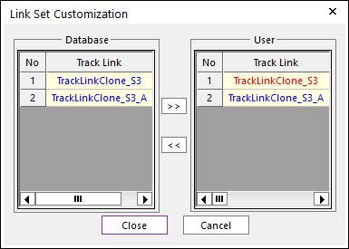
Figure 3 Link Set Customization dialog box
•Link Set Customization
o The user cannot move the first link and can compose user’s link by the database’s link.
o The composed link set is marked in the RMD file.
•Estimation: The user can estimate the assembled links.
•Auto Link No. Calculation: If the user clicks Estimation with the checked this option, the number of links is set automatically.
•Number of Links: Modifies the number of links.
•Pin Gap: Shows a value of pin gap.
•Automatic Sprocket Alignment: If this option is checked, the sprockets are rotated to match the position of the links.
•Note: If there are interference between a sprocket and a link after finishing assembly with this option, the alignment is failed.
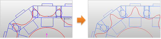
Figure 4 After using ‘Automatic Sprocket Alignment’ option