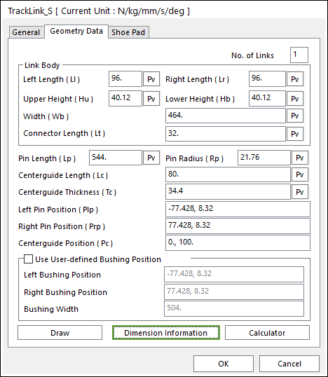
Figure 1 Single Pin Track Link property page [Geometry Data page]
The Single Pin Track Link property page is shown in Figure 1. The parameters are explained below. In order to understand the geometry, refer to Dimension Information.
•No. of Links: Generates a link or links as the number of setting links.
•You can generate from one to five.
•The generating links can be edited in the clone body.
•It is same to apply in Track_HM (Single, Double, Inner Pin Track link) and Track_LM.
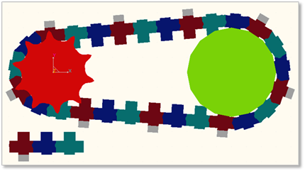
Figure 2 Example of three link sets
•Link Body: Defines geometric characteristics for Link Body.
•Left Length (Ll): Enters the left length of link.
•Right Length (Lr): Enters the right length of link.
•Upper Height (Hu): Enters the upper height of link.
•Lower Height (Hb): Enters the lower height of link.
•Width (Wb): Enters the width of link.
•Connector Length (Lt):
•Pin Length (Lp): Enters the length of pin body.
•Pin Radius (Rp): Enters the radius of pin body.
•Centerguide Length (Lc): Enters the length of center guide body.
•Centerguide Thickness (Tc): Enters the thickness of center guide body.
•Left Pin Position (Plp): Enters the position of left pin body.
•Right Pin Position (Rrp): Enters the position of right pin body.
•Centerguide Position (Pc): Enters the position of center guide body.
•Use User-defined Bushing Position: If it is checked, Bushing force can be defined on different position with pin position.
•Left Bushing Position: Defines a base marker position of Bushing force
•Right Bushing Position: Defines an action marker position of Bushing force
•Bushing Width: Defines a width between two bushing forces.
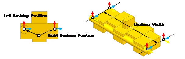
Figure 3 Dimension information of user-defined bushing position
•Draw: Shows the shoe pad geometry. The user can change the position and size. Also, the shoe pad geometry can be modified in Shoe Pad page.
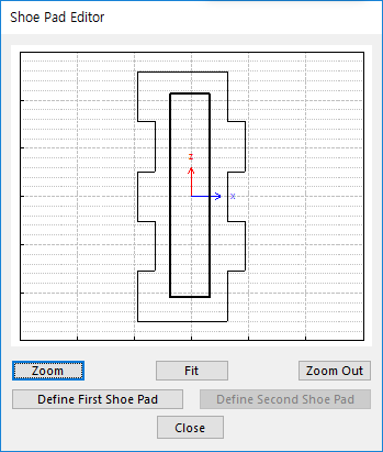
Figure 4 Shoe Pad Editor dialog box
•Define First Shoe Pad: The user can create a shoe pad by a mouse in Draw dialog box. It can be available in the link.
•Define Second Shoe Pad: If Double Shoe Pad in Shoe Pad page is used, this function is activated. The user can create a shoe pad by a mouse in Draw dialog box. It can be available in the link.
•Dimension Information: Shows dimension information of the geometry for Roller Link.
•Calculator: It is useful for finding specific value to define the relation of between sprockets and Track links. For more information, click here.