A track shoe pad is fixed on the track link body. The track shoe pad bears the machine weight and exerts traction to the ground. The shoe pad geometric entity is designed cautiously because it receives different force such as normal force and shear forces. There are two types for vehicle soil interactions. One is hard ground contact and the other is soft soil contact according to Bekker’s theory. Shoe points are needed in hard ground contact and shoe pad mesh is needed in the soft soil.
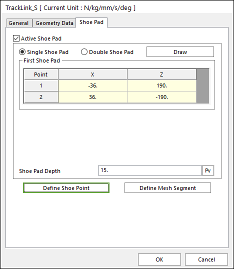
Figure 1 Track Link property page [Shoe Pad page]
•Active Shoe Pad: If it is checked, shoe pad can be used.
•Shoe Pad Shape
There are various types of shoe pad suitable for different work purposes and ground conditions, such as the specially designed shoe pad which has a low ground pressure on the soft ground. In RecurDyn/Track_HM, a single shoe pad and double shoe pad are given.
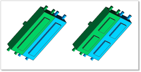
(a) Single shoe pad (b) Double shoe pad
Figure 2 Shoe pad shape
•Shoe Pad Depth: Defines a depth of the shoe pad.
•Define Shoe Point: Shoe points are used to define interaction between the track link body and the hard ground. The default shoe points are supported as follows.
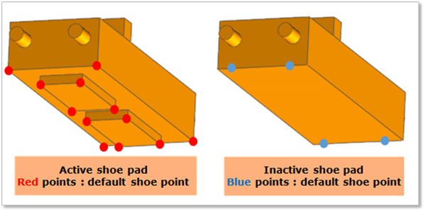
Figure 3 Default shoe point
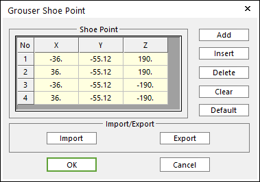
Figure 4 Grouser Shoe Point dialog box
•X, Y, Z: Defines points.
•Add: Adds a row to the end of the table.
•Insert: Adds new row to the selected row by the mouse cursor and move the current and lower rows down.
•Delete: Deletes the selected row by the mouse cursor and move the lower rows up.
•Clear: Deletes all rows in the table.
•Default: Resets modified data.
•Import: Imports the X, Y, and Z data pairs from a CSV file or a MAT file or a text file. In the case of the text file, the usage of the comma, the tab, and the space can be the delimiter between the three columns in the file. And when using the Excel file, the user can select the Tab-delimited text file output option or the CSV (Comma-Separated Values) file output option to save the Excel file which can be imported.
•Export: Exports the X, Y, and Z data pairs to a CSV file or a MAT file or a text file.
If the shoe points are set with a regular form, then the RecurDyn solver generates some patch information for the Node Contact of the Track Surface Contact.
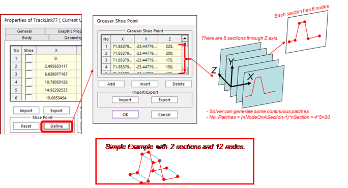
Figure 5 Contact patches for the Grouser Shoe
•Define Mesh Segment: When a vehicle runs on a soft soil, it is not sufficient to define contact by points. Therefore, more points must be provided to form patches on the surface of shoe pad. To achieve this goal, length, height and depth of shoe pad can be meshed into segment.
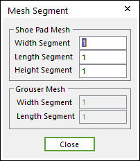
Figure 6 Mesh Segment dialog box
•Shoe Pad Mesh: If Active Shoe Pad function is checked, Shoe Pad can be meshed to 3 directions.
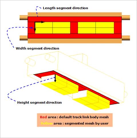
Figure 7 Shoe Pad Mesh
•Grouser Mesh: If Active Shoe Pad function is not checked, Grouser can be meshed to 2 directions.
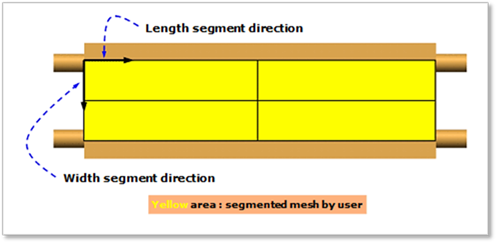
Figure 8 Grouser Mesh