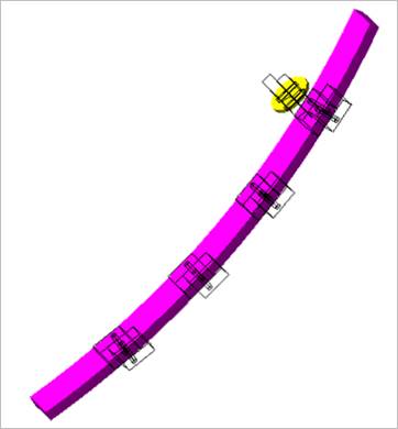
Figure 1 Tensioner Guide
Click Geometry of Tensioner Guide in the Component Builder dialog box. And then the user can see the dialog box.
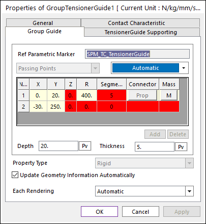
Figure 2 Group Tensioner Guide property page [Group Guide page]
•Ref Parametric Marker: Shows the reference parametric marker.
•X,Y.Z: Defines a passing point of the guide based on Ground Inertia Marker.
•R: Defines a radius of the guide passing two points
•Segments: Defines the number of segments in the guide.
•Connector: If Property Type is RSDA or Beam, the use can modify the property by clicking Prop.
•Depth: Defines a depth of the guide.
•Thickness: Defines a thickness of the guide.
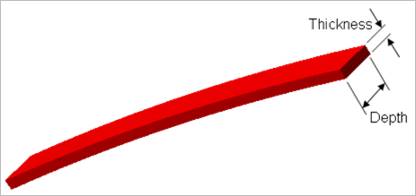
Figure 3 Definition of depth and thickness of Tensioner Guide
•Property Type: Selects a connecter type between segments. Rigid, RSDA, and Beam type are supported. The user can modify properties of connector by clicking Prop.
•Rigid: All guide segments are connected by fixed joints.
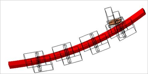
Figure 3 Rigid type of Tensioner Guide
•RSDA: All guide segments are connected by the revolute joints and rotational spring damper. For more information, refer to Rotational Spring supported as a Force entity.
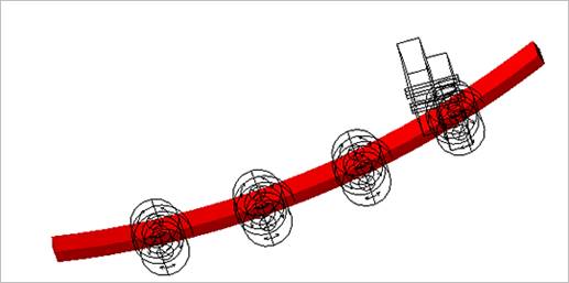
Figure 4 RSDA type of Tensioner Guide
•Beam: All guide segments are connected by beam elements. For more information, refer to Beam supported as a Force entity.
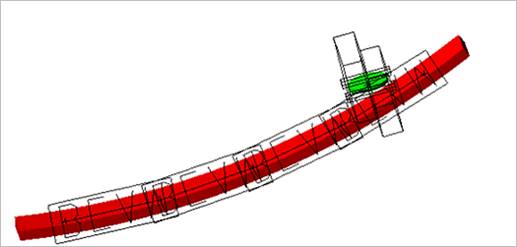
Figure 5 Beam type of Tensioner Guide
•Each Rendering: The selected mode can be displayed in Each Render mode. For more information, click here.