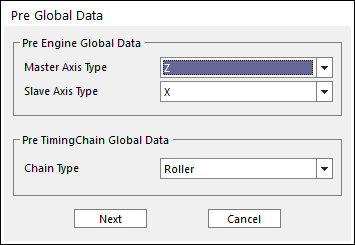
7. Click the Data icon of the Timing Chain group in the Timing Chain tab. The user can see Pre Global Data dialog box.

Figure 1 Pre Global Data dialog box
•Master Axis Type: Defines the rotational axis and direction of crank shaft.
•Slave Axis Type: Defines the direction of cylinders based on the master axis.
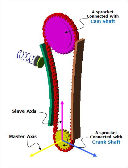
Figure 2 Master & Slave Axis of Timing Chain System
•Chain Type
•Roller chain type
•Silent chain type
8. Previous defined values are the basic information to create a timing chain system. After these data are confirmed, each value is unchangeable. So if Next is clicked, the warning message is displayed.
9. After that, Timing Chain Global Data Dialog is opened as follow.
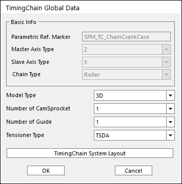
Figure 3 TimingChain Global Data dialog box
•Name: Means that the values the user entered are defined in Global Data.
•Parametric Ref. Marker: Checks the parametric marker for crank system. SPM_TC_ChainCrankCase controls the whole system. It cannot be modified.
•Model Type
•3D: Is selected, the full contact algorism is applied.
•2D: Is selected, the 2D approach is applied for the contact between sprockets and links without considering the depth direction contact. The 2D approach is faster than the 3D approach.
•Number of CamSprocket: Input the desired value. This value is available up to 4.
•Number of Guide: Input the desired value. This value is available up to 4.
•Tensioner Type
All types of tensioner are explained in System Component Builder.
•TSDA
•HAT
10. Click TimingChain System Layout in Figure 3. And then following dialog box can appear.
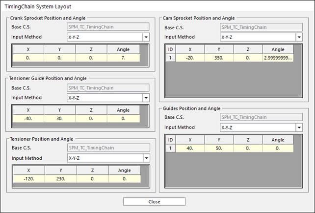
Figure 4 TimingChain System Layout dialog box
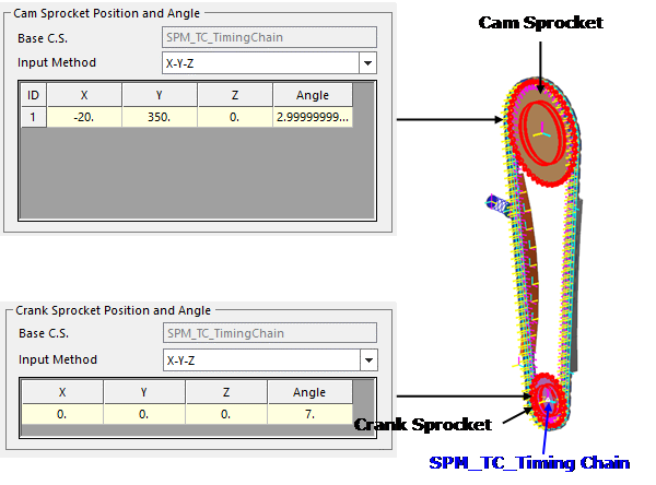
Figure 5 Timing Chain Layout
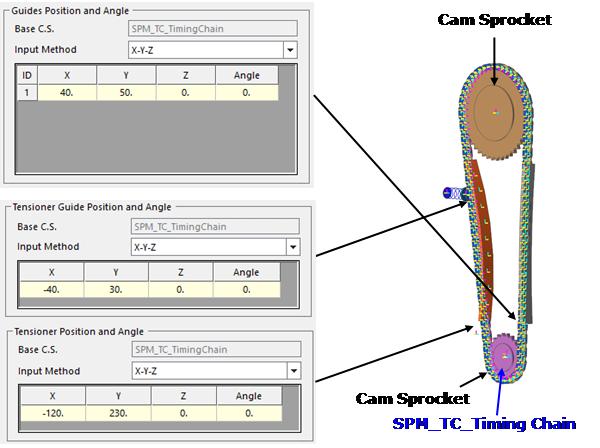
Figure 6 Timing Chain System Layout
11. After setting all parameters, click Close in Figure 6. And Click OK in Figure 3.
12. Up to here, all global data are defined for the basic structure of timing chain. Please follow the next step.