Shell Belt is constructed with shell4 elements. The shell4 elements are the same FFlex/Shell4 element (3D and Plane stress shell type element). All nodes of shell4 have 6 DOFs.
Coordinate System
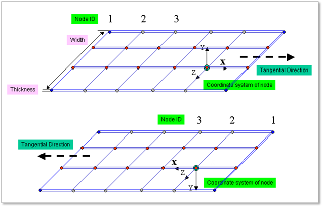
Figure 1 Coordinate system of the belt body
•The node is described as a sphere.
•The center marker is located at the central point of sphere and its orientation is dependent on the direction used when the belt is created as shown in Figure 1.
•If you apply the plus values in the initial velocity of belt, the belt moves into the plus direction of the x-axis of the center marker of each belt body.
•The shell force markers of each belt body are located at the center marker and their orientations are the same orientation of each center marker.
Mass and Moment of Inertia
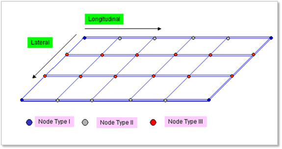
Figure 2 Nodal Masses and Moments of Inertia
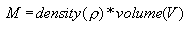
•Total mass (M):
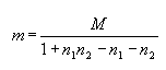
•Mass coefficient (m):


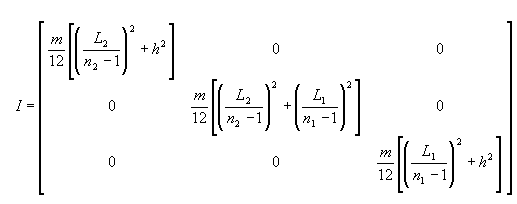
•Moments of Inertia (I):


•Nodal masses:
 For nodes at four corners
 For nodes on four edges
 For internal nodes
•Nodal moments of inertia:
 For nodes at four corners
 For nodes on four edges
 For internal nodes
Contact Geometry of Shell Belt
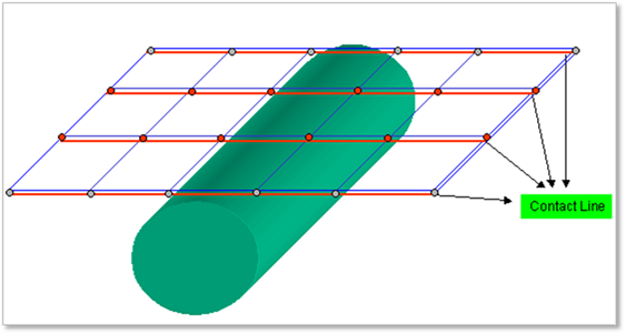
Figure 3 Contact geometry of belt
The contact geometry of belt is approximated as the contact lines as shown in Figure 3.
The parameters used to define the contact between the belt and the rollers can significantly influence the solving time of a model. Because of the very small masses in the belt, the contact force is very sensitive to contact parameters. The higher stiffness and damping values can reduce the numerical stability.