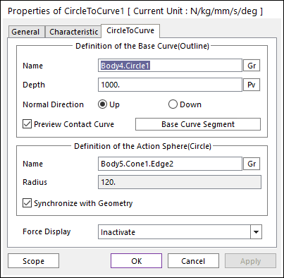
Figure 1 Properties of CircleToCurve dialog box
•Definition of The Base Curve (Outline)
•Entity Name: Defines the name of a base curve or outline. The base curve or outline can be dispatched from the Working Window by clicking Gr
•Depth: Defines the depth of the contact face of the base curve. The user can change Depth as the parametric value by clicking PV.

Figure 2 Preview of the Normal direction and Points
•Normal Direction: Defines the normal direction of a base curve or outline for a contact as shown in Figure 2.
o The contact is available in the specified direction.
o As selecting “Up” or “Down”, the user can change the contact direction of a base curve or outline.
o If this page is activated, the normal direction is automatically shown on the Working Window.
•Preview Contact Curve: If this option is checked, the points making the contact lines are shown on the Working Window as shown in Figure 2.
•Base Curve Segment: Accesses Base Curve Segment dialog box as show in Figure 3.
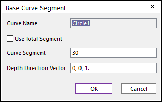
Figure 3 Base Curve Segment dialog box
o Use Total Segment: If this option is selected, the user can make equally spaced contact points on the curve. For more information, click here.
o Curve Segment: Defines the number of segments between a start node and an end node. For more information, click here.
o Depth Direction Vector: Defines the direction vector of contact surface extruded from the curve. The normal vector is determined by this direction.
•Definition of The Action Sphere(Circle)
•Entity Name: Defines the name of action sphere or circle. The user can change the action sphere by using the navigation method.
•Radius: Shows the radius of action sphere or circle. This value is automatically determined by the radius of the action geometry but if the user turn off the Synchronize with Geometry option, the user can directly input the radius or change it as the parametric value by clicking PV.
•Synchronize with Geometry
o If this option is checked, Radius in Contact Properties is automatically defined with that of the specified graphic.
o If this option is not checked, the user can modify the contact properties.
•Force Display: Graphically displays the resultant force vector on the view window. For more information, click here.