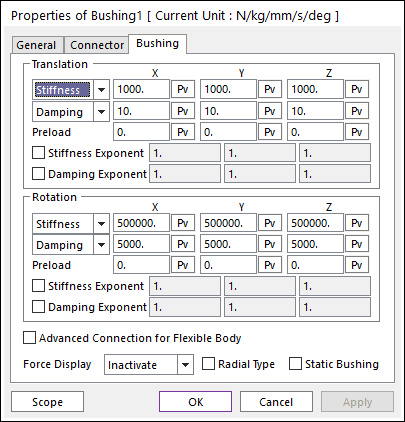
Figure 1 Bushing property page
The magnitude of the busing force is calculated according to the following equations:
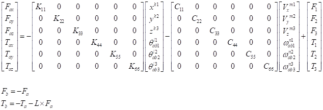
Where, the inputs into the equation are defined in the following table:
|
Stiffness X, Y, Z (Translation) |
|
Enter the coefficient that determines spring stiffness, namely the change in bushing displacement from the equilibrium position as a function of the force in the respective direction (units are force/length). |
|
Stiffness Spline X, Y, Z (Translation) |
|
Fill in values of spring lengths and spring forces that will cover the range of extension and retraction of the spring. For more information, click here. |
|
Damping X, Y, Z (Translation) |
|
Enter the coefficient that determines the damping force given the velocity of motion in the bushing in the respective direction (units are force-time/length). |
|
Damping Spline X, Y, Z (Translation) |
|
Fill in values of spring velocities and damping forces that will cover the range of positive and negative velocities in the spring. For more information, click here. |
|
Preload X, Y, Z (Translation) |
|
Specify an extra load or force in the spring in the respective direction. The force in the bushing in its equilibrium position is the Preload. |
|
Stiffness Exponent (Translation) |
|
Specify an exponent that is applied to the rate of change of the spring length (spring velocity). |
|
Damping Exponent (Translation) |
|
Specify an exponent that is applied to the velocity of motion in the bushing. |
|
Displacement X, Y, Z (Translation) |
|
Translational displacements of the action marker with respect to the base marker. |
|
Velocity X, Y, Z (Translation) |
|
Translational velocities of the action marker with respect to the base marker |
|
Stiffness X, Y, Z (Rotation) |
|
Enter the coefficient that determines spring stiffness, namely the change in bushing displacement from the equilibrium position as a function of the force in the respective direction (units are force-length/radian). |
|
Stiffness Spline X, Y, Z (Rotation) |
|
Fill in values of spring rotations and spring torques that cover the range of rotation of the spring. For more information, click here. |
|
Damping X, Y, Z (Rotation) |
|
Enter the coefficient that determines the damping force given the velocity of motion in the bushing in the respective direction (units are force-length-time/radian). |
|
Damping Spline X, Y, Z (Rotation) |
|
Fill in values of spring rotational velocities and damping torques that will cover the range of positive and negative velocities in the spring. For more information, click here. |
|
Preload X, Y, Z (Rotation) |
|
Specify an extra load or force in the spring in the respective direction. The force in the bushing in its equilibrium position is the Preload. |
|
Stiffness Exponent (Rotation) |
|
Specify an exponent that is applied to the change in bushing displacement from the equilibrium position. |
|
Damping Exponent (Rotation) |
|
Specify an exponent that is applied to the velocity of motion in the bushing. |
|
Displacement X, Y, Z (Rotation) |
|
Rotational displacements of the action marker with respect to the base marker. |
|
Velocity X, Y, Z (Rotation) |
|
Rotational velocities of the action marker with respect to the base marker |
•Advanced Connection for Flexible Body: If user selects this option, the bushing force is directly connected two body not using virtual body connection. If there’s no flexible body (RFlex or FFlex), this option is ignored.
•Force Display: Displays the resultant force vector graphically on Working Window. For more information, click here.
•Radial Type: If the user checks Radial Type option, a translational x direction of bushing force and a translational y direction of bushing force are combined. The magnitude of the radial type busing force is calculated according to the following equations:
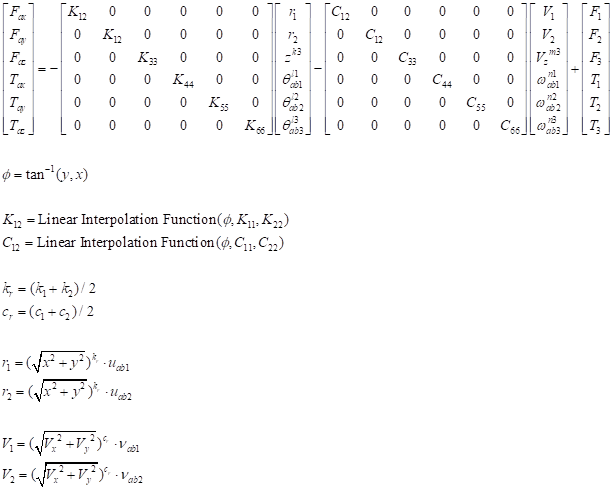
where,
 : Radial angle
 : Radial stiffness coefficient and
damping coefficient
: Radial stiffness coefficient and
damping coefficient
 : Radial exponents
 : Radial displacement direction
factor
: Radial displacement direction
factor
 : Radial velocity direction
factor
: Radial velocity direction
factor
•Static Bushing: If the user checks Static Bushing option, a bushing force is used only executing Static analysis. When executing Dynamic/Kinematic analysis, a bushing force is not used.
Note
When the relative angle is evaluated, RecurDyn/Solver assumes that the difference of the rotation range for the x-axis and y-axis is small.