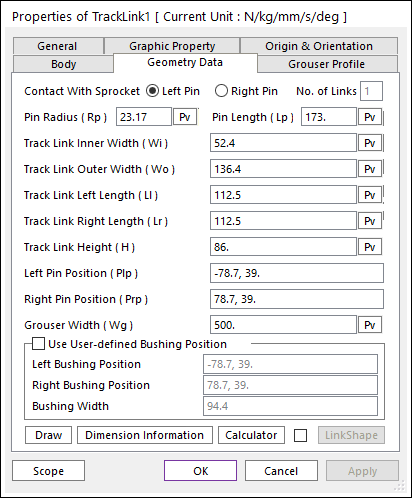

Figure 1 Track Link property page [Geometry Data page]
The Track Link property page is shown in Figure 1. The parameters are explained below. In order to understand the geometry, refer to Dimension Information.
•Contact With Sprocket: The Left/Right Pin of track(LM) link can be selected to calculate more accurate friction force of sprocket with link pin.
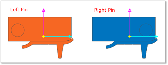
Figure 2 The position of Link Pin as Contact With Sprocket option
•No. of Links: Defines the number of link sets. This can be available when creating a track link clone body.
•Pin Radius (Rp): Enters the pin radius of link.
•Pin Length (Lp): Enters the pin length of link.
•Track Link Inner Width (Wi): Enters the inner width of link.
•Track Link Outer Width (Wo): Enters the outer width of link.
•Track Link Left Length (Ll): Enters the left length of link.
•Track Link Right Length (Lr): Enters the right length of link.
•Track Link Height (H): Enters the height of link.
•Left Pin Position (Plp): Enters the left pin position of link.
•Right Pin Position (Prp): Enters the right pin position of link.
•Grouser Width (Wg): Enters the width of grouser.
•Use User-defined Bushing Position: If it is checked, Bushing force can be defined on different position with pin position.
•Left Bushing Position: Defines a base marker position of Bushing force
•Right Bushing Position: Defines an action marker position of Bushing force
•Bushing Width: Defines a width between two bushing forces.

Figure 3 Dimension information of user-defined bushing position
•Draw: All data must be defined with respect to the grouser marker. You can move points graphically by using the mouse directly. Also, the grouser geometry can be modified in Grouser Profile page.
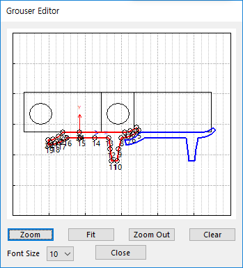
Figure 4 Grouser Editor dialog box
•Dimension Information: Shows dimension information of the geometry for Roller Link.
•Calculator: It is useful for finding specific value to define the relation of between sprockets and Track links. For more information, click here.
•Link Shape: The link tread is subjected to uneven wear due to constant contact with the idler and rollers. The link shape can be modified in order to consider the wear effect.
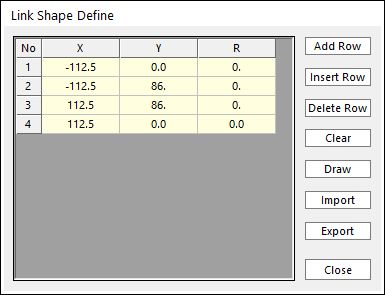
Figure 5 Link Shape Define dialog box
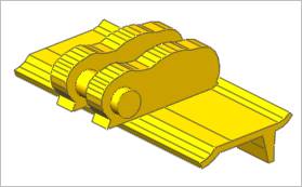
(a) Modified link shape
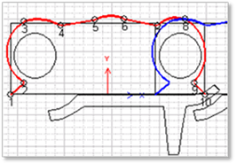
(b) Link shape editor
Figure 6 Changing the link shape