A track grouser is fixed onto the track link by grouser bolts and nuts. The track grouser bears the machine weight and exerts traction to the ground. The grouser geometric entity is designed cautiously because it receives different force such as normal force and shear forces.
There are two types of vehicle-soil interaction. One type is hard ground contact and the other is soft soil contact according to Bekker's theory. Shoe points are needed in hard ground contact and a grouser mesh is needed in soft soil. Also, grouser nodes have to be chosen if grouser to sphere contact is defined to represent contact with boulders and rocks.
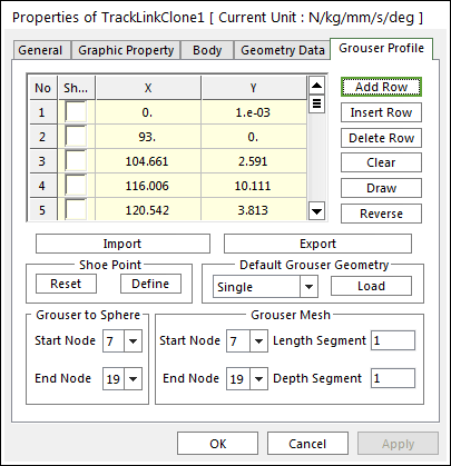
Figure 1 Track Link property page [Grouser Profile page]
•No:
•Shoe
•X, Y: Defines points.
•Add Row: Adds a row to the end of the table.
•Insert Row: Inserts a row where the cursor is and move the current and later rows down.
•Delete Row: Deletes the row where the cursor is and move the later rows up.
•Clear: Deletes all rows in the table.
•Draw: All data must be defined with respect to the link grouser marker. You can move points graphically by using the mouse directly.
•Reverse: Change the direction of the grouser.
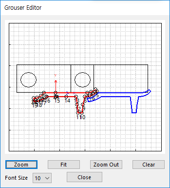
Figure 2 Grouser Editor dialog box
•Import: Imports the X and Y data pairs from a CSV file or a MAT file or a text file. In the case of the text file, the usage of the comma, the tab, and the space can be the delimiter between the three columns in the file. And when using the Excel file, the user can select the Tab-delimited text file output option or the CSV (Comma-Separated Values) file output option to save the Excel file which can be imported.
•Export: Exports the X and Y data pairs to a CSV file or a MAT file or a text file.
•Shoe point: Shoe points are used to define interaction between the track link grouser and hard ground. The points are selected from points on the grouser profile by checking on the first column of Grouser Geometric Entity Data on the grouser dialog box.
•Reset
•Define: Modify the position of shoe points in the following dialog box.
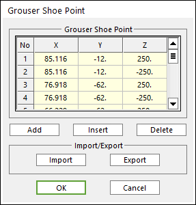
Figure 3 Grouser Shoe Point dialog box
o X, Y, Z: Defines points.
o Add: Adds a row to the end of the table.
o Insert: Adds new row to the selected row by the mouse cursor, and move the current and lower rows down.
o Delete: Deletes the selected row by the mouse cursor, and move the lower rows up.
o Import: Imports the X, Y, and Z data pairs from a MAT file or a text file. In the case of the text file, the usage of the comma, the tab, and the space can be the delimiter between the three columns in the file. And when using the Excel file, the user can select the Tab-delimited text file output option or the CSV (Comma-Separated Values) file output option to save the Excel file which can be imported.
o Export: Exports the X, Y, and Z data pairs to a MAT file or a text file.
•Default Grouser Geometry: There are various types of grousers suitable for different work purposes and ground conditions, such as the specially designed grouser that has a low ground pressure on soft ground. Single, Double and Triple grousers are available in RecurDyn/Track_LM,

(a) Single (b) Double (c) Triple
Figure 4 Grouser Geometry
•Grouser to Sphere: An object such as a stone buried in the ground is often simply defined as a sphere. Contact between a grouser and a sphere is defined by contact points on the grouser profile. If the user defines a Starting Node and an Ending Node of the grouser, all nodes between two nodes become contact points for Grouser to Sphere Contact.
•Grouser Mesh: When a vehicle runs on soft soil, it is not sufficient to define contact by points. Therefore, more points must be provided to form patches on the surface of a grouser. To achieve this goal, the length and depth of a grouser can be meshed into segment. For example, when the starting node number is 5 and the ending node number is 13, the length segment is 2 and the depth segment is 4, the track link grouser is meshed as follows.
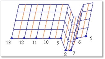
Figure 5 Grouser mesh