
Figure 1 Inner Pin Track Link property page [Geometry Data page]
•Left Length (Ll): Enters the left length of link.
•Right Length (Lr): Enters the right length of link.
•Upper Height (Hu): Enters the upper height of link.
•Lower Height (Hb): Enters the lower height of link.
•Pin Length (Lp): Enters the length of pin body.
•Link Width (Wb): Enters the total width of link.
•Inner Width(Wcnti): Enters the width of liner link body.
•Outer Width(Wcnto): Enters the width of outer link body.
•Left Pin Pos (Plp): Enters the position of left pin body.
•Right Pin Pos (Rrp): Enters the position of right pin body.
•Pin Radius (Rp): Enters the radius of pin body.
•Centerguide Pos (Pc): Enters the position of center guide body.
•Genterguide
•Length (Lc): Enters the length of center guide body.
•Thickness (Tc): Enters the thickness of center guide body.
•Contact Cylinder Position
•Left (Plcnt)
•Right (Prcnt)
•Contact Radius(Rcnt)
•Shoe Radius(Rs)
•End Connector Length (Le)
•Draw: Shows the shoe pad geometry. The user can change the position and size. Also, the shoe pad geometry can be modified in Shoe Pad page.
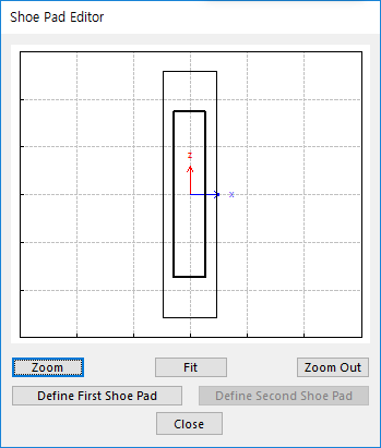
Figure 2 Shoe Pad Editor dialog box
•Define First Shoe Pad: The user can create a shoe pad by a mouse in Draw dialog box. It can be available in the link.
•Define Second Shoe Pad: If Double Shoe Pad in Shoe Pad page is used, this function is activated. The user can create a shoe pad by a mouse in Draw dialog box. It can be available in the link.
•Dimension Information: Shows dimension information of the geometry for Roller Link.
•Calculator: It is useful for finding specific value to define the relation of between sprockets and Track links. For more information, click here.