Figure 1 Sheet To Surface Contact property page
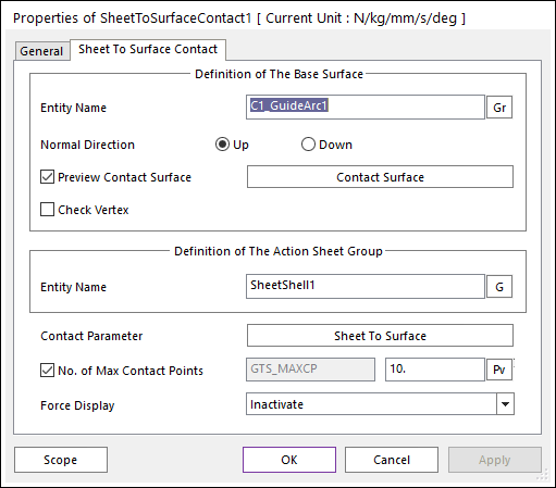
Figure 1 Sheet To Surface Contact property page
•Entity Name of The Base Surface: Select the base surface by using Gr.
•Normal Direction: Defines the normal direction of a base surface for a contact as shown in Figure 1.
•Preview Contact Surface: If this button is checked, the patches making the contact surface and its boundary box are displayed.
•Contact Surface: Accesses Surface Patch dialog box as shown figure. For more information, click here.
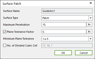
Figure 2 Surface Patch dialog box
•Entity Name of The Action Sheet Group: Select the action sheet by using G.
•Contact Parameter: Allows the user to modify contact parameters by clicking Sheet To Surface. In this dialog box, the user can modify the contact parameters of contact forces applied between the sheet and the surface. Refer to the Contact Formulus for MTT3D.
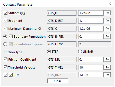
Figure 3 Contact Parameter dialog box
•No. of Max Contact Points: Defines the number of max contact point for output. User can define this value from 1 to 5000. This value only affects Force Display and RPLT data about the contact points. The default value is 10.
•Force Display: Graphically displays the all contact force vectors (the sum of the normal and tangential contact force) at each contact point up to the “No. of Max Contact Point”.
•Check Vertex: When the size of a guide is smaller than that of a contacted shell element, the contact will not be worked. In this case, if this option is on, the four vertexes of the guide are checked in the sheet-to-guide contact.