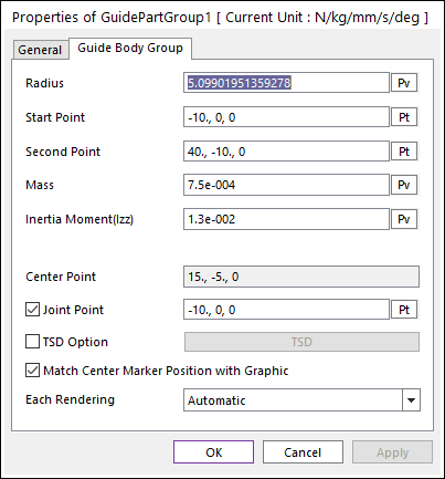
The properties dialog box of the Guide Body Group has two tabs.

Figure 1 Guide Body property page
•Radius: Defines the radius of guide body.
•Start Point: Defines the start point of guide body.
•Second Point: Defines the end point of guide body.
•Mass: Defines the mass of guide body.
•Inertia Moment (Izz): Defines the mass Moment of Inertia with respect to the z-axis of the center marker.
•Center Point: Is the position of the center of the mass marker.
•Joint Point: Defines the position of revolute joint.
•TSD Option: If the user checks this option, the user can be active Translational Spring Damper (TSD) force. The user can modify TSD properties by clicking TSD.

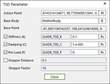
Figure 2 TSD Parameter dialog box
•Action Point: Defines the position of action marker of TSD force applied on the action body.
•Base Body: Defines the name of base body
•Base Point: Defines the position of base marker of the TSD force applied on the base body.
•Stiffness (K): Defines the stiffness coefficient of the TSD.
•Damping(C): Defines the damping coefficient of the TSD.
•PreLoad (F): Defines the pre-Load applied to the TSD.
•Stopper Distance, Stopper Factor: Refer to Guide Group.
•Each Rendering: The selected mode can be displayed in Each Render mode. For more information, click here.